HandyVent - An Easy-To-Build Ventilator
With the spread of COVID-19 there is a need for ventilators to help people with severe lung inflammation survive the disease. The USA healthcare system has a big shortage of these now when they are needed dearly.We set out to design a reusable, functionally-complete, and intrinsically safe ventilator that can be made with off-the-shelf parts and minimal tools, suitable for use with COVID and ARDS patients. We intentionally chose parts which are available from hardware stores and generic vendors, so that anyone can build this ventilator without needing special supply chains, machine equipment, 3D printers, or advanced manufacturing technologies. Only household tools are needed, and it is possible for anyone who is handy to quickly build these ventilators without special manufacturing needs. Our hope is that no one needs to be "last in line" for a ventilator because a big manufacturer can't prioritize them, or doesn't ship to their country.
 These stages of operation are as follows:
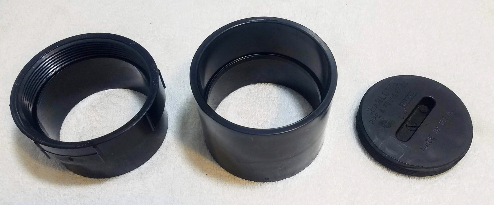 You will also need the following tools:
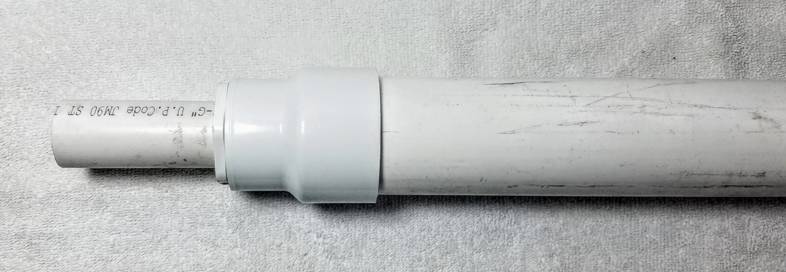 Now you must install a plug, cap, or otherwise to your 4" pipe so that cannot leak if filled with water. Depending on what hardware you have available, you might need to use thread sealing tape and PVC glue to prevent water from leaking out of the pipe.
 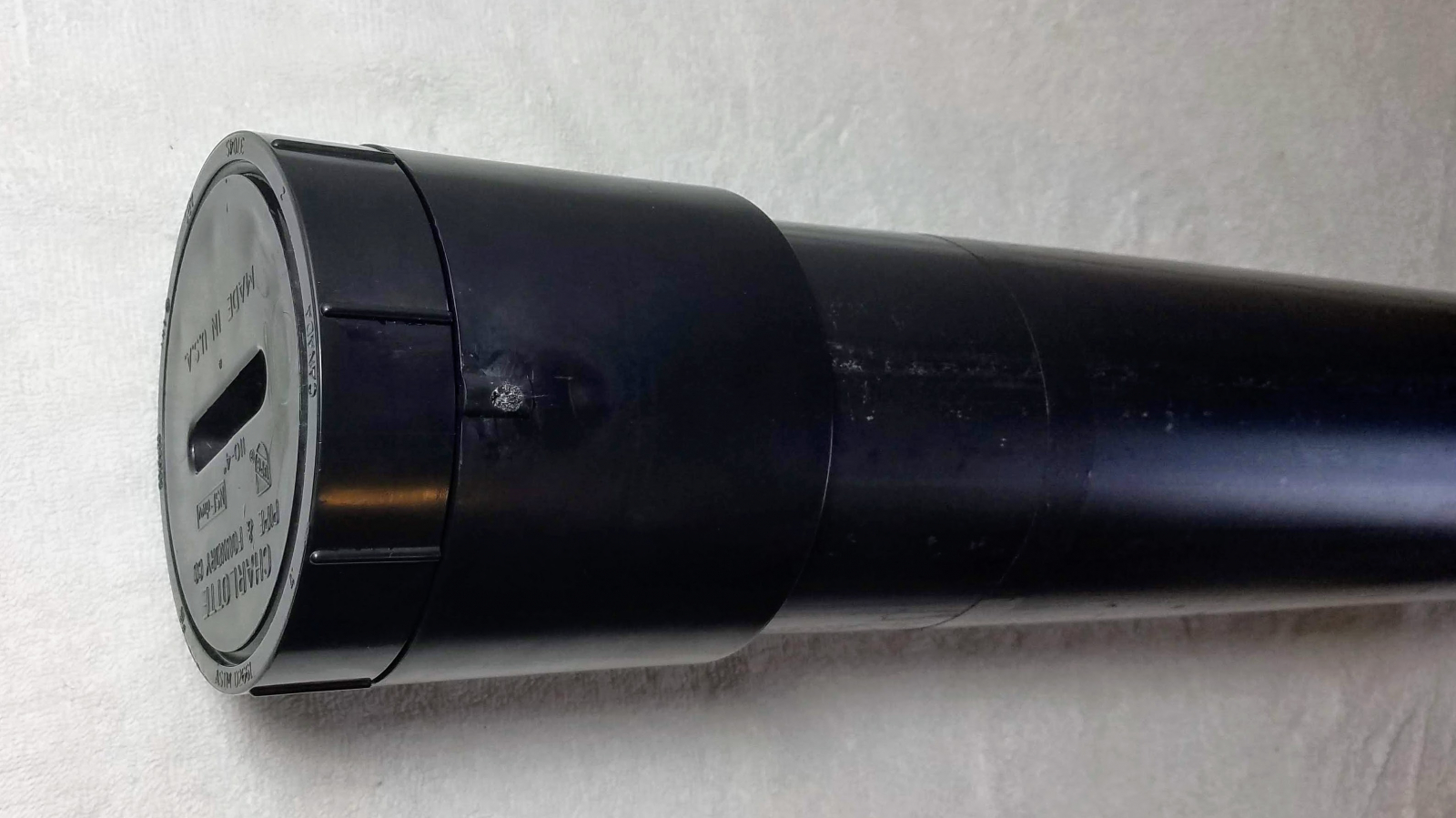 In our case, using thread sealing tape on the 4 inch coupling thread was necessary.
 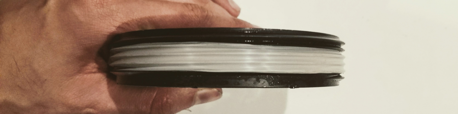 After you have capped the pipe, you must drill an 11/16" hole 8 centimeters from the inner bottom of the pipe. The inner bottom being defined as the place where, if the 2 inch pipe were to be inserted, it would come to rest and not go any further. In our case, this was conveniently 2cm south of the coupling ring we use to hold the female thread adapter in place.
 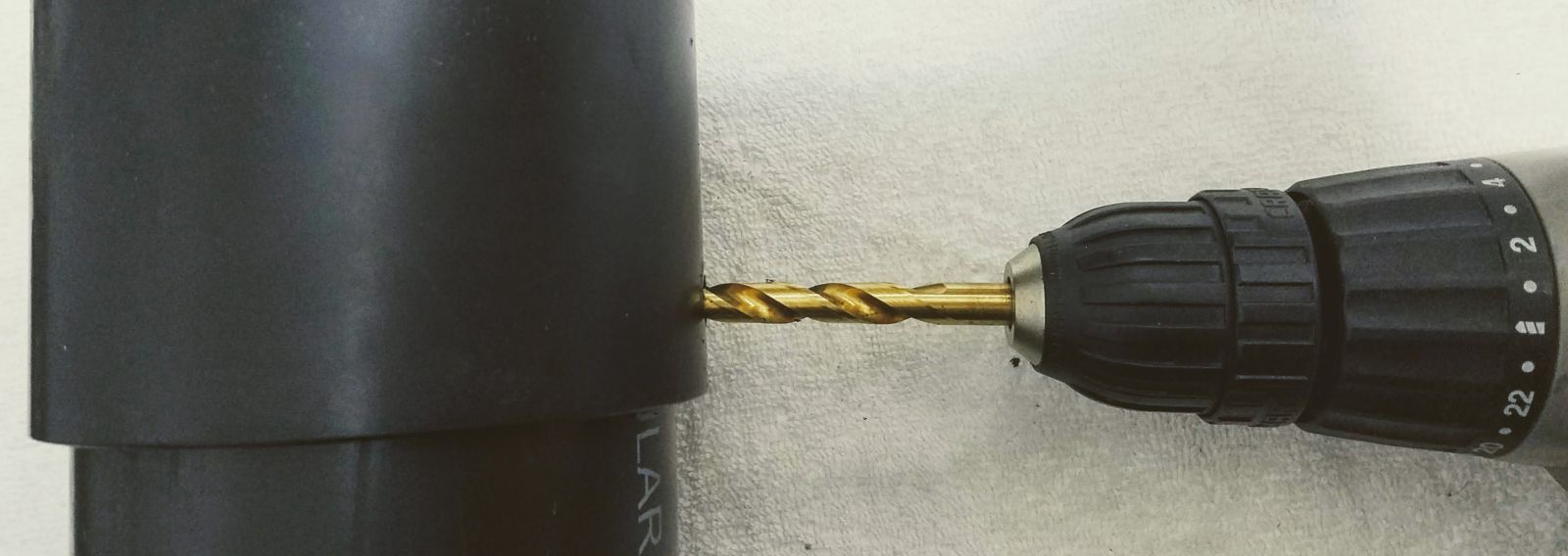 Next, use your adjustable wrench to install the brass hose barb into the hole you just made. The plastic is much softer than the brass, so the brass will create and seal its own thread. Take care not to over-tighten the barb once it is all the way in, or you may destroy your threads. Afterward, install the vinyl hose on the barb.
 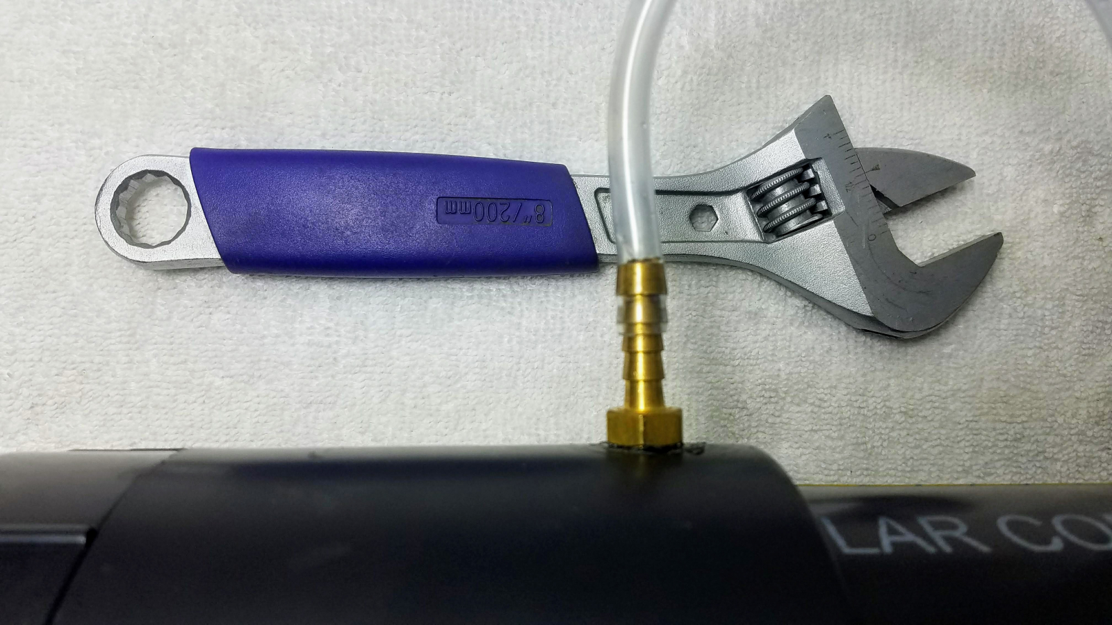 Next, use your light colored vinyl tape and permanent marker to create graduations on the pipe, with the first mark being 10cm, and the last mark being 45 cm. You can then use the black vinyl tape to affix the 1/4" hose right next to the graduations, taking care to allow enough bending radius to not kink the hose.
 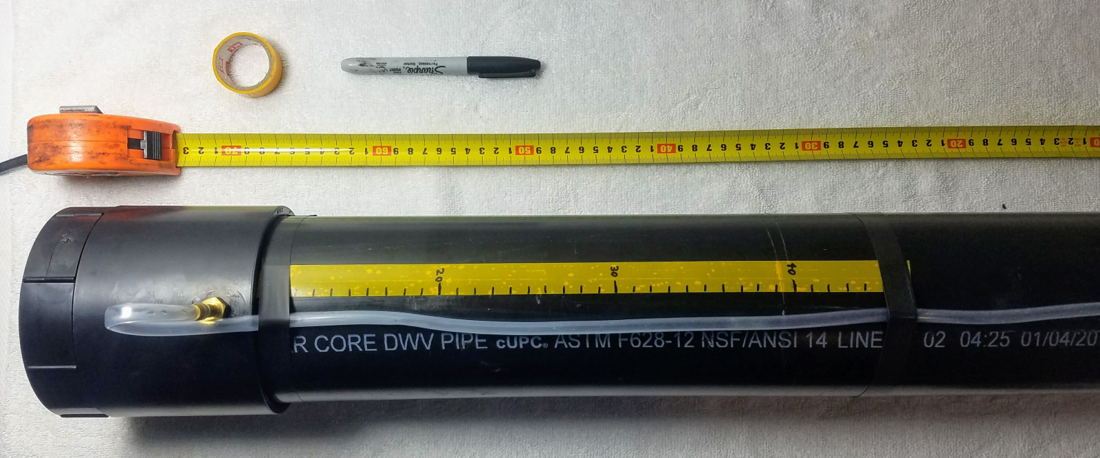 Once this is done, install your tidal volume chamber into the PIP chamber by placing the 2" pipe section inside the 4" pipe section. You can then fill the 4" pipe with water to a level which sets the appropriate inspiratory pressure.
 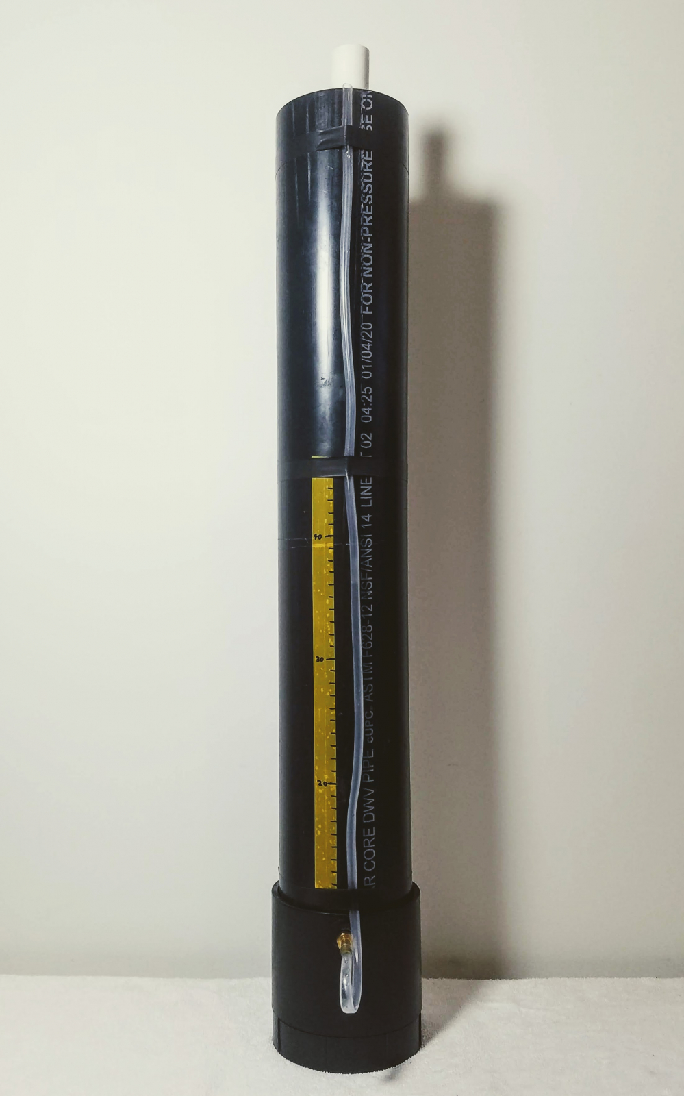 The manometer hose will allow whomever is monitoring the ventilator to make sure that the inpsiratory pressure is within a safe range, and that the air is cycling in and out of the lung as anticipated. The water level shown when the machine is off will be the Minimum Inspiratory Pressure, and the highest water level shown when the machine is cycling, is the Peak Inspiratory Pressure. As the tidal volume fills, the pressure will increase, and as the tidal volume empties, the pressure will decrease to the minimum inspiratory pressure. The momentum of the water keeps the air motion very smooth and gentle on the lungs. If you have the parts, it is possible to install a valve at the bottom of the manometer to let water out of the chamber without a siphon. We recommend you do this for production as it greatly simplifies adjusting PIP pressure.
 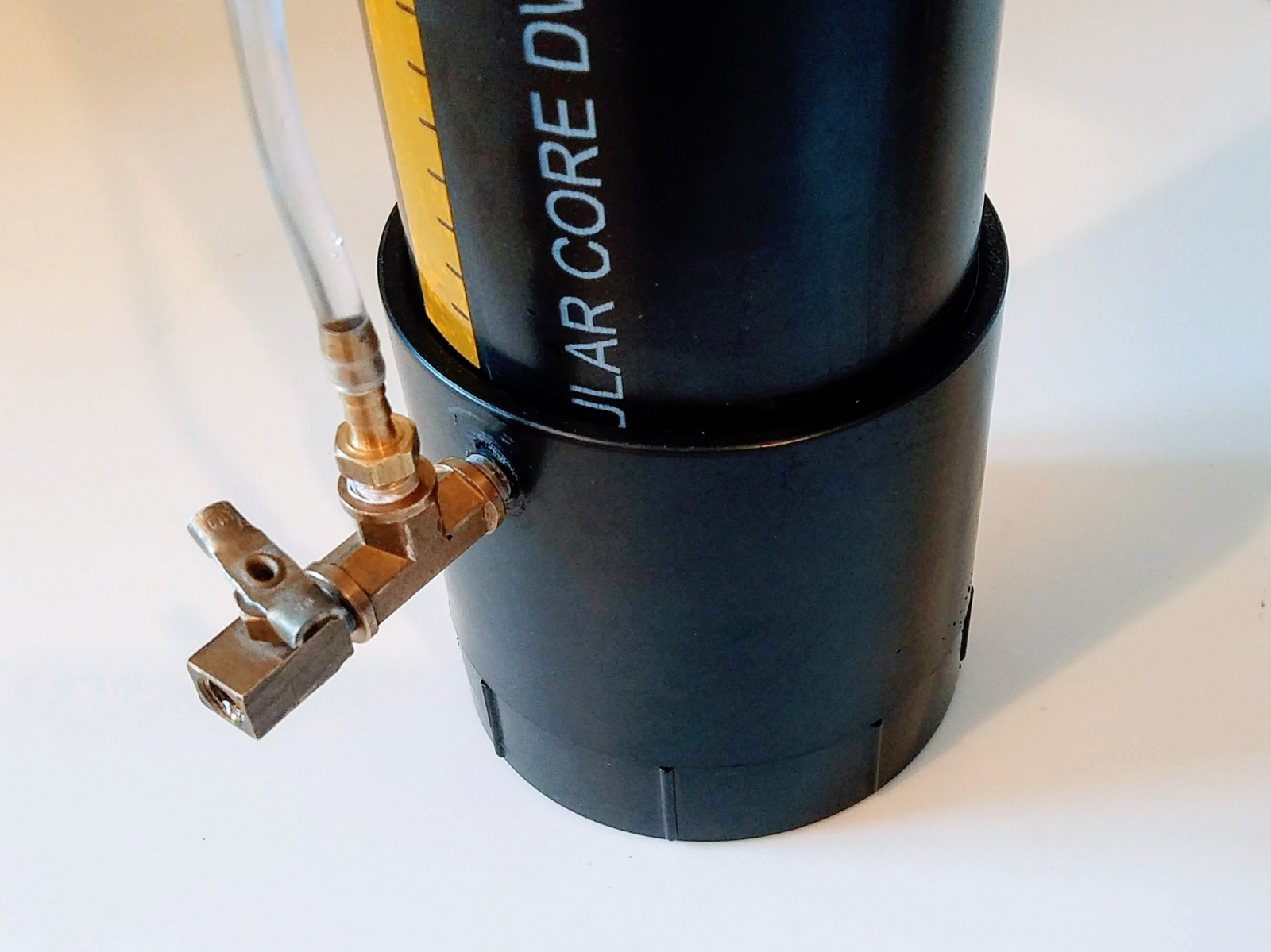 Any input pressure which exceeds the peak inspiratory pressure will bubble out of the tidal volume chamber, protecting the patient from any over-pressure that might otherwise occur. Unless the water freezes, this regulator should be extremely reliable and difficult to incorrectly manufacture, which is why it is our method of choice.
 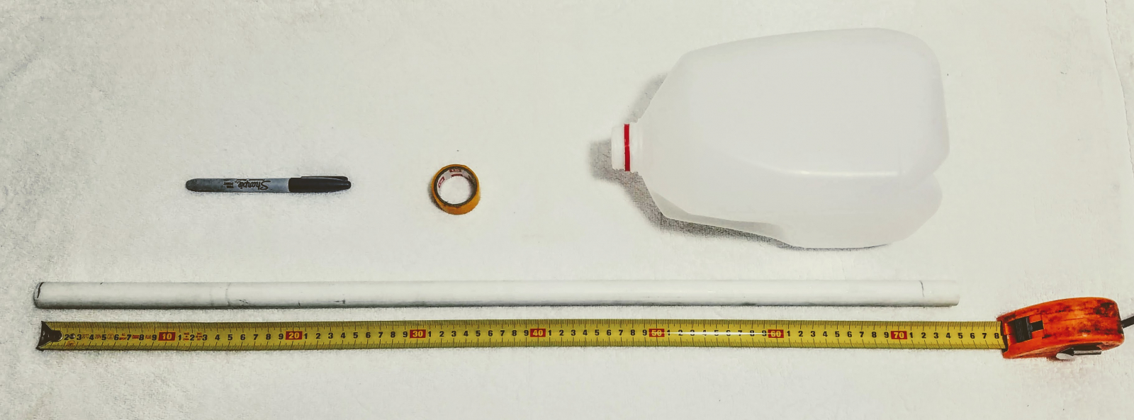 We need to add graduations so that the PEEP pressure can be set by the person using the ventilator. To do this, we can lay out some light-colored tape next to a measuring rule, and transfer the markings from the rule onto the tape.
 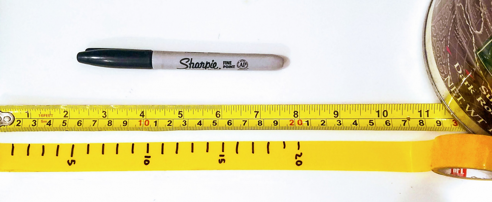 Afterwards, we install the tape on the milk carton, measured from the bottom. This allows us to fill the carton with water and immediately know the PEEP that will be needed to exhale through the assembly. It is very important to not shorten the PVC pipe, as its height is intentionally chosen to make it impossible to inhale the fluid from the PEEP chamber. If you shorten this pipe, you take a risk that water flows backward into the hoses which is very bad indeed.
 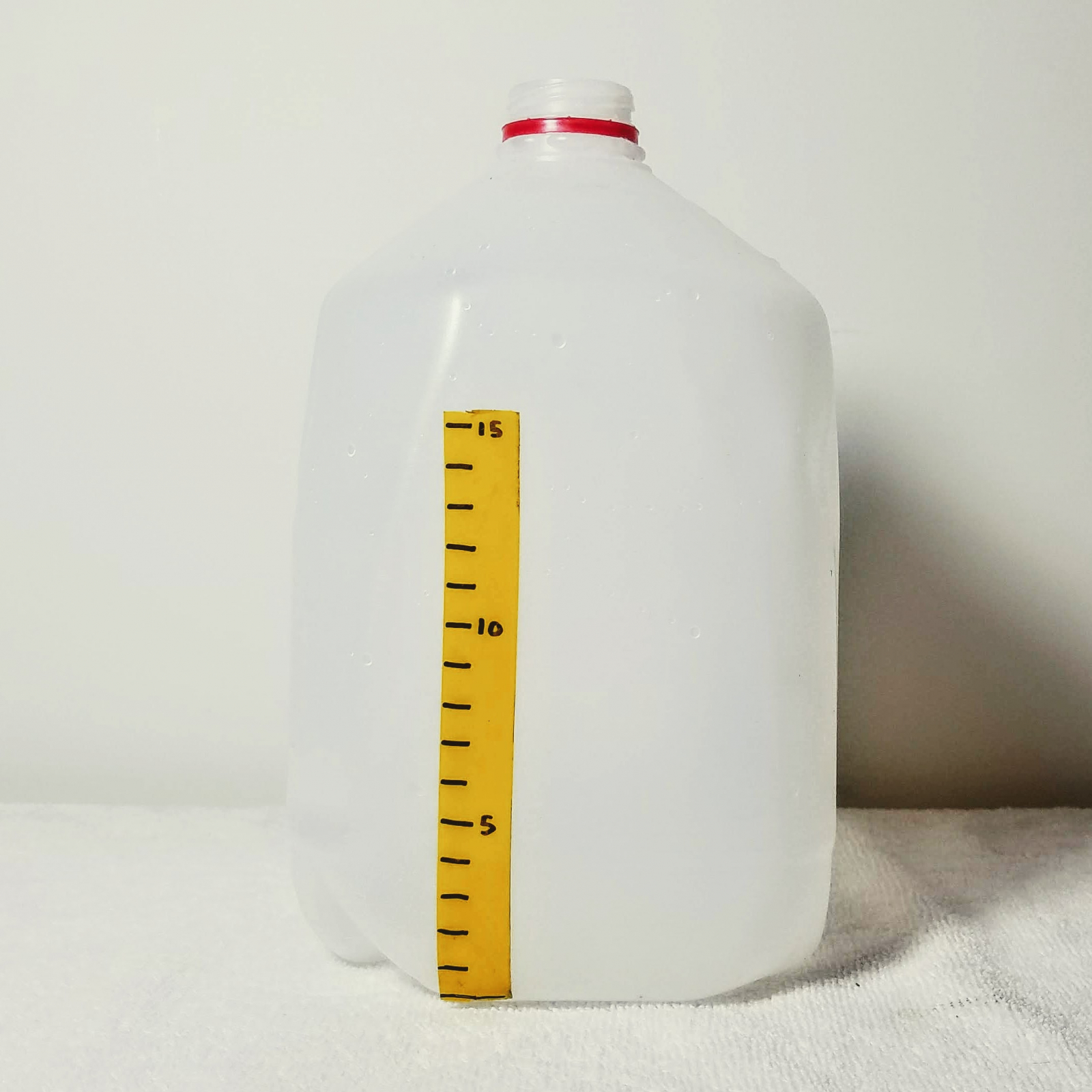 Insert the PVC pipe into the chamber, and your PEEP chamber is now complete! You may now add alcohol, chlorine bleach, or hydrogen peroxide to the water which will aid in keeping it sterile.
 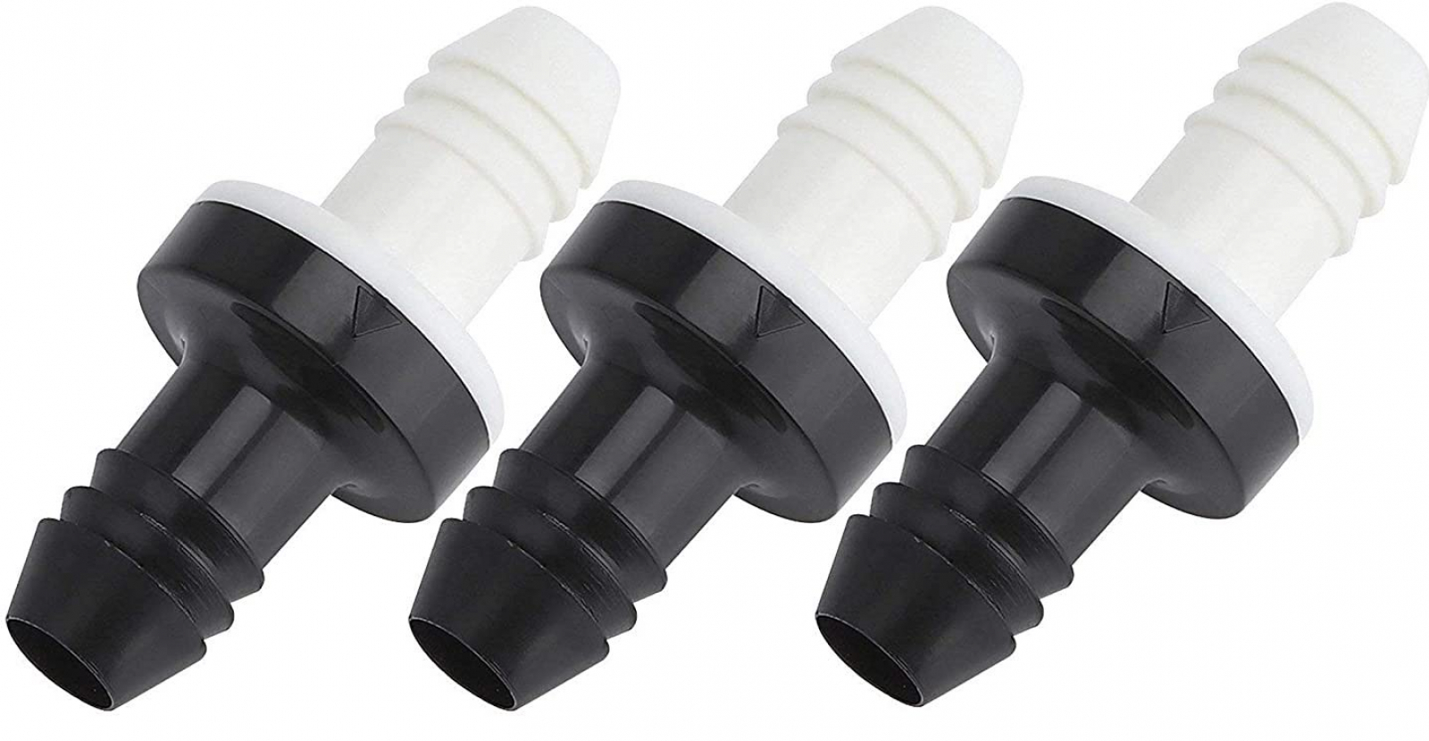 The most important consideration is that the valve uses a silicone duck-bill element inside, as these have a low working pressure (0.5kPa or less) which is suitable for breathing air, and that the valve has at least a 3/8" or 10mm diameter hose barb. These valves don't pass enough air alone to be suitable for breathing, but you can put a few of them in parallel for increased airflow. We have found that three is the minimum number required. To build the check valve, you will need:
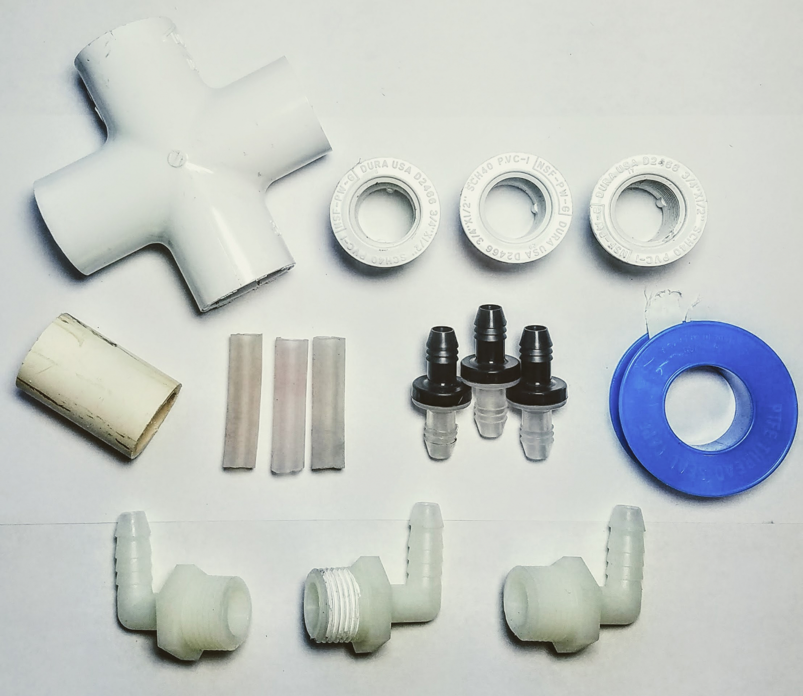 To assemble the check valve, first combine the three adapters, valves, silicone hoses, and bushings together. The check valves should be oriented in such a way as to allow flow inward toward the bushing, and not outward toward the environment. You may use PTFE thread sealing tape to improve the seal between the bushings and the hose barbs, but it might not be needed since the working pressures are very low.
 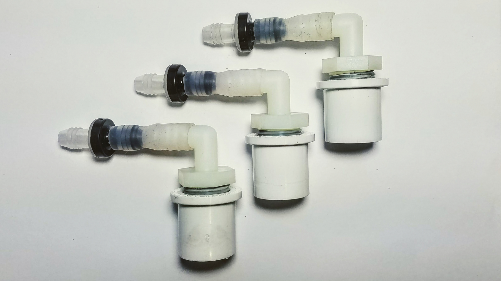 Next, take these three valves and insert them into the PVC cross. We did not find that any glue was necessary, and a friction-fit was sufficient. As well, take the 5cm length of 3/4" PVC pipe and insert it into the last port of the cross. You may glue this in for security.
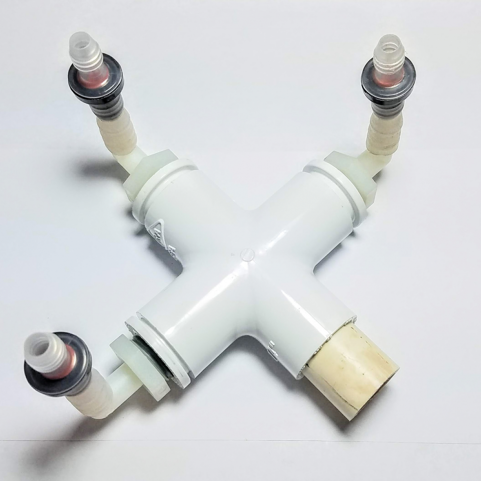 Your check valve is now complete!
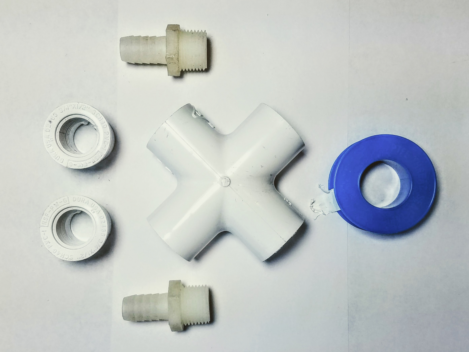 It is pretty straightforward to assemble this, just take the hose barbs and bushings and install them the only way which is possible. Afterward, you may take the check valve and install it into the cross without glue, leaving you with something that looks like this:
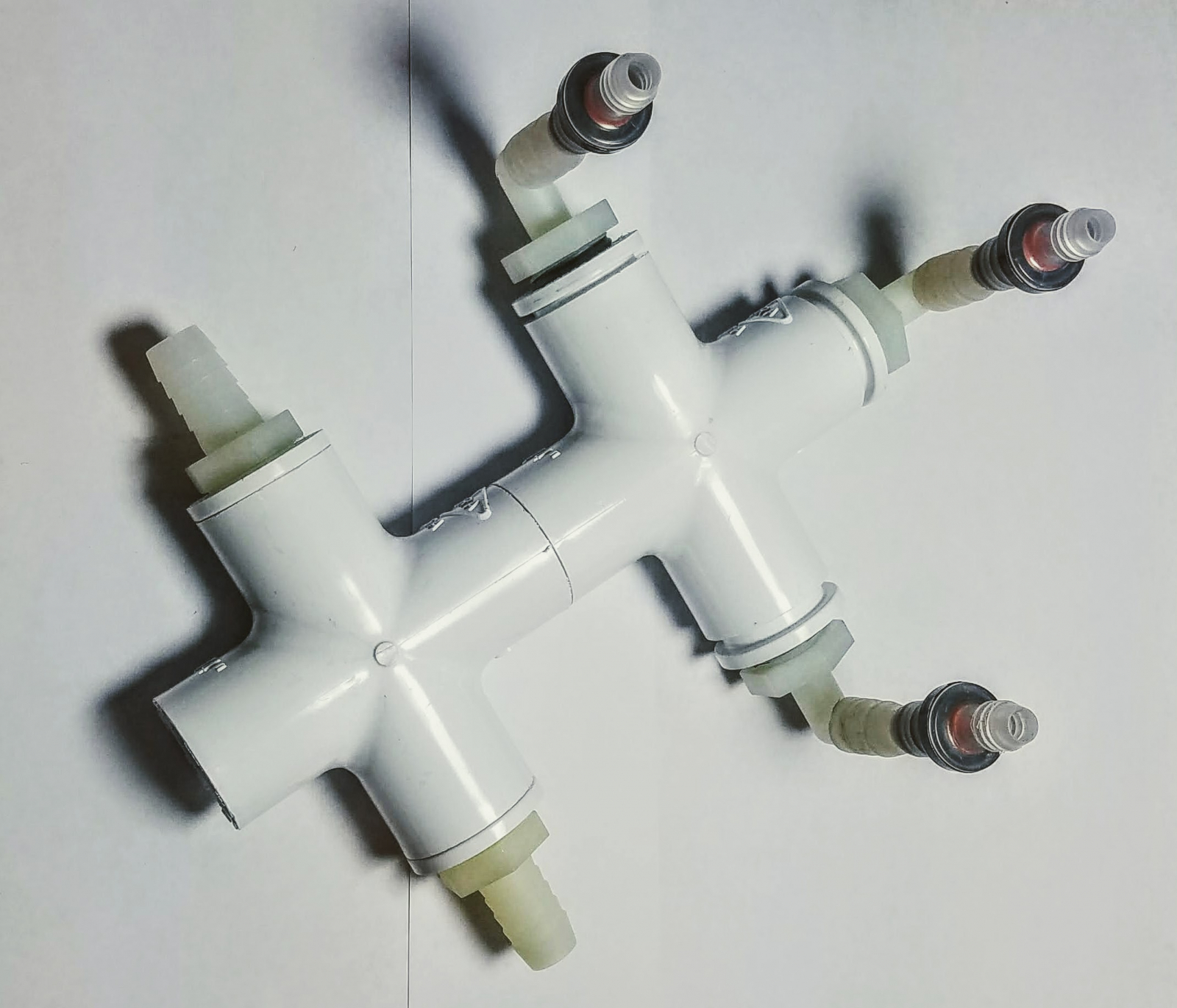 This whole assembly may be sterilized in a pressure cooker and reused numerous times, so be sure to build it well!
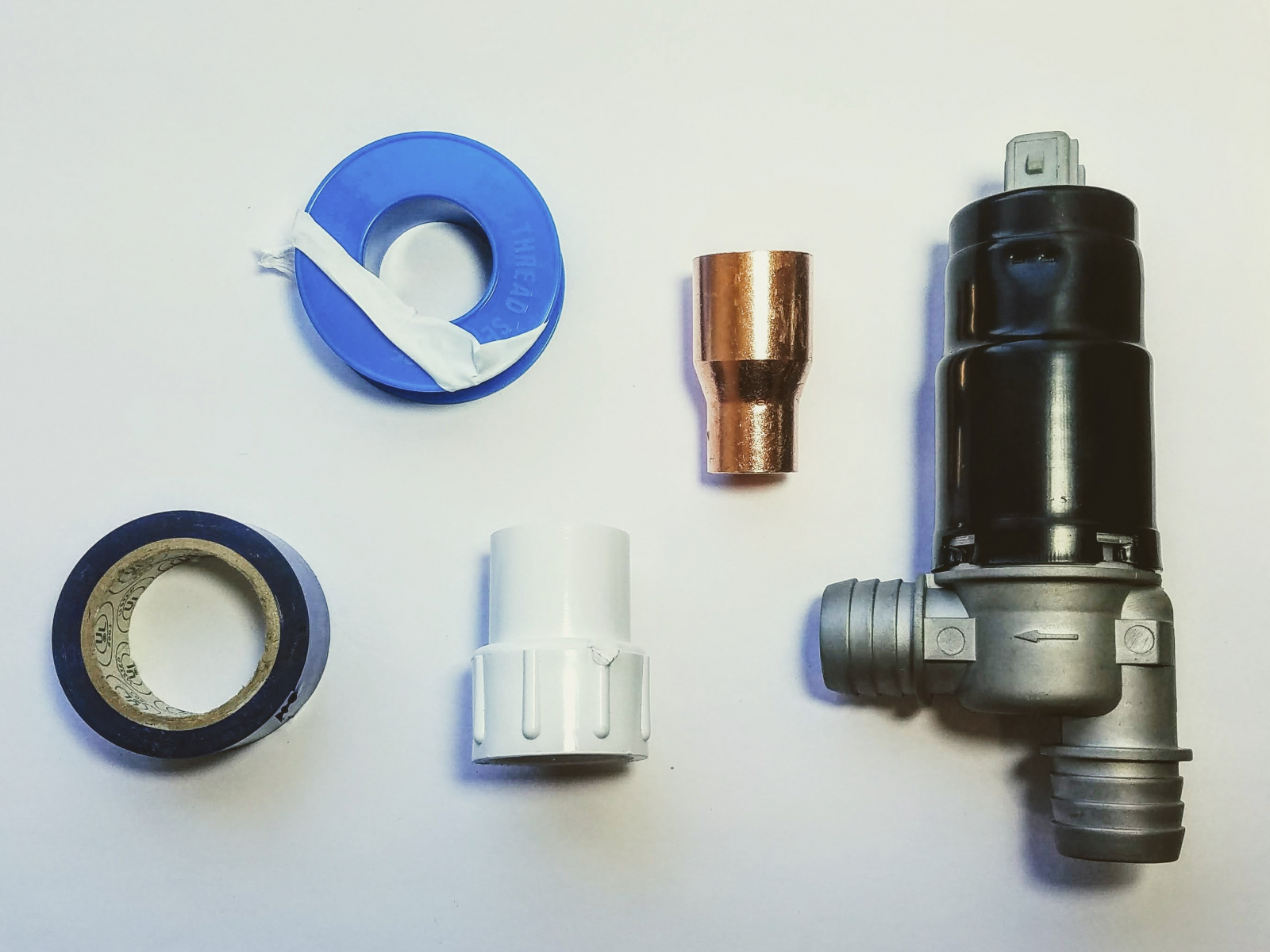 You will need to use the copper fitting and vinyl tape to make the barb small enough to accept a 1/2" silicone hose. You will also need to use a significant amount of PTFE thread sealing tape to make the other barb large enough to fit into a 3/4" FIP PVC coupling. Here we used only a little vinyl tape to show how the barb and copper mate, however you should use as much as needed to make sure the copper cannot come off the barb. You may also use silicone self-sealing tape, 2-part epoxy, or hose clamps and rubber tubing to make the connection if you have these materials available.
 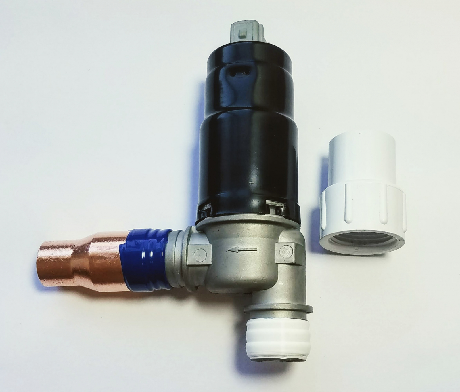 When you screw the PVC fitting onto the valve, it won't be a tight fit. However, it should seal well enough to prevent the air from escaping. If it does not, add more PTFE tape and try again.
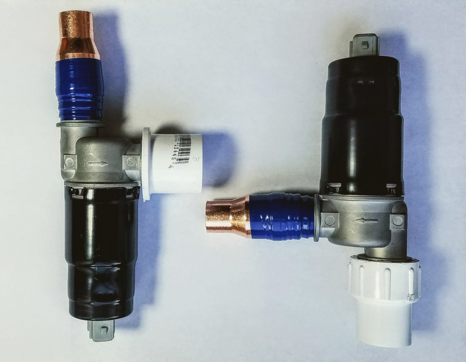
 The completed inlet valve should look like this: there is only one way to construct it.
 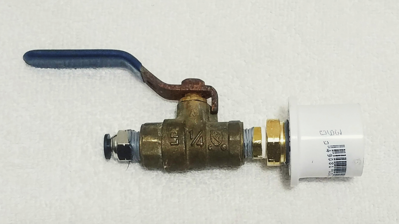 Afterward, install the inlet valve and the inhalation valve to the top of the PIP chamber using a 1" PVC tee. No glue should be needed, as friction is capable of holding all these parts in place.
 ![]()
 The other ends of the hoses must be affixed to the mask port in a similar way. Afterwards, we clearly marked the inlet and outlet ports, as well as the mask port with the permanent marker.
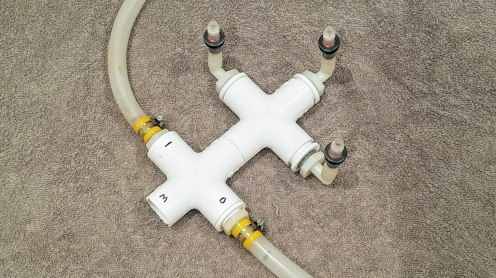
 We used heater hose that had a double-wall, which gave it the appropriate internal and external diameter for the mask and PVC fitting. If you do not have this kind of hose, you may need to get creative inn affixing the 22mm CPAP fitting to the 1, 1/16" inner diameter of the mask port.
 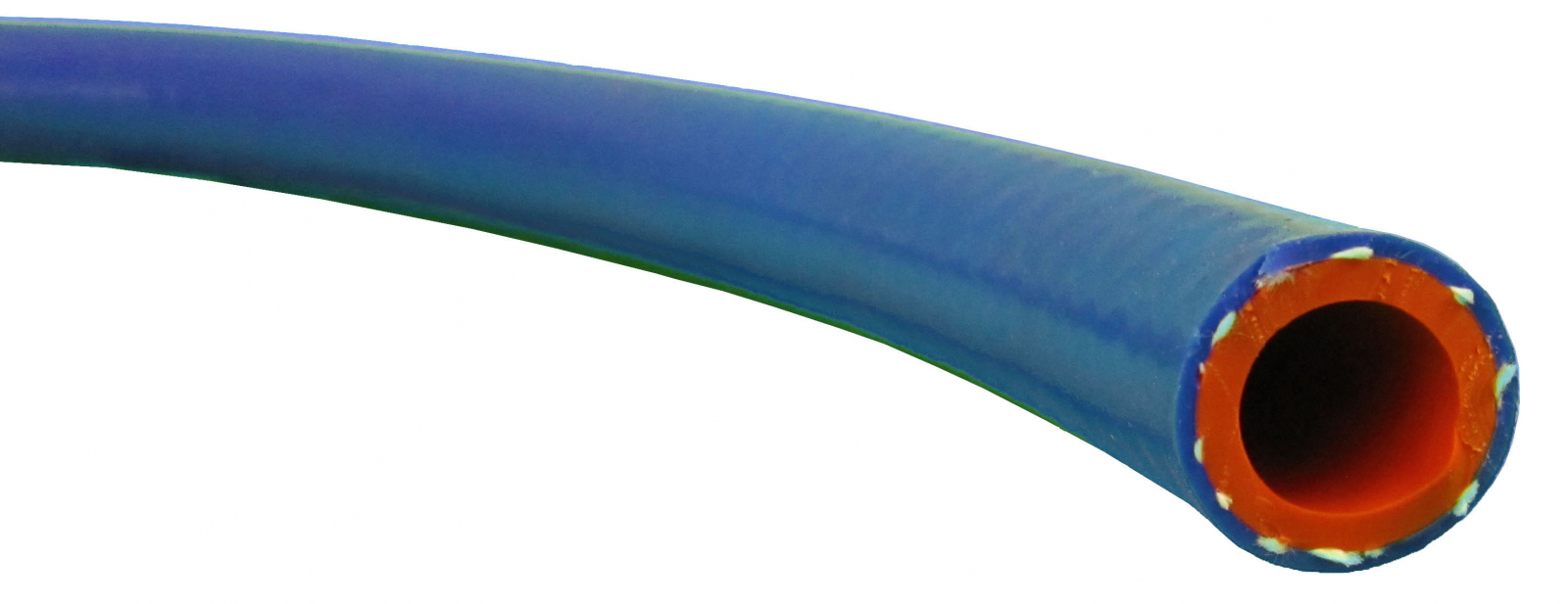 You will need to modify the mask to seal off any openings. The mask we chose has a number of small ventilation holes on the mask body, and a check-valve inside the rotating arm of the mask. We found that vinyl tape was sufficient to plug these holes, but it is possible that RTV silicone can make a more durable seal.
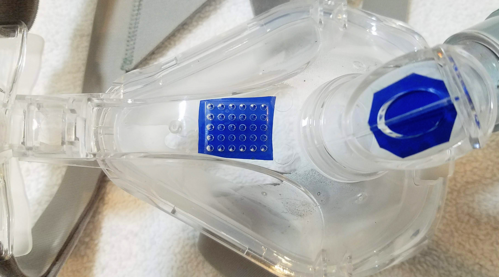 To affix the CPAP mask to the inlet, we use a small section of silicone heater hose. It is flexible enough to stretch over the 22mm inlet port without needing any additional hardware to stay secured. As well, its outer diameter is perfect to insert into the PVC cross. Now this hose must be kept short! If it is too long, then the patient will be inhaling and exhaling the same air over and over again, which can lead to suffocation.
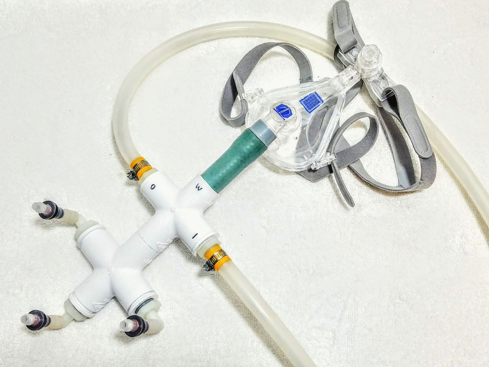
 This compressor's output is 70LPM with no back-pressure, but, we found that due to our leaky valves, two of the 70LPM compressors were needed to power the ventilator. We combined the output of these compressors using pneumatic quick-connect fittings and tees, which proved to be reliable enough for the application.
 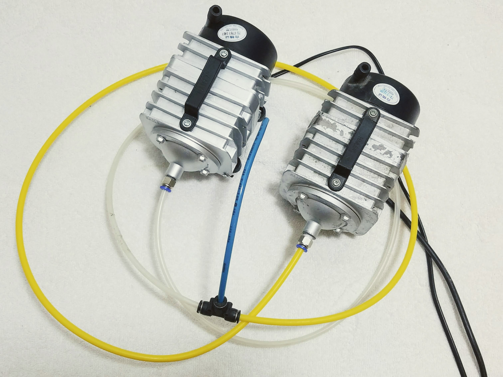 You can also get these compressors in larger sizes, up to 224 LPM (3566 GPH). We have not tested these however, and are not sure if they are as reliable as the 70 LPM compressors. It is important that these free-piston compressors receive sufficient airflow to stay cool, so do not put them in a closed container unless you also install a fan in that container. Helpful Ideas:It is very possible that a shop-vac used in reverse could work sufficiently well, but we have not tried this. Alternatively, a centrifugal blower may work well also.
 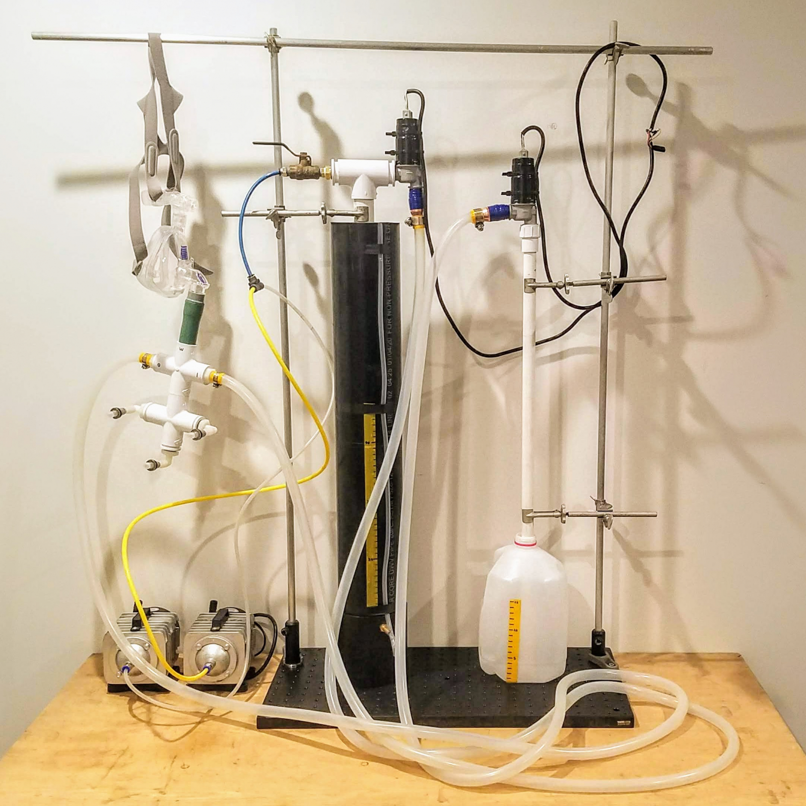 We are using chemistry lab equipment to hold everything in place, but wood can be used if this is not available. It is certainly possible to make the fixtures adjustable (help wanted), so that the pipework can be moved to adjust the PEEP pressure instead of changing the fluid level in the peep chamber, but we have not done this in the interest of publishing this design as quickly as possible. You can add supplemental oxygen to the air stream with another quick-connect tee. Here we are using a Phillips Respironics Everflo, which outputs approximately the same pressure as our compressors and helps increase the O2 content of the ventilator's gas.
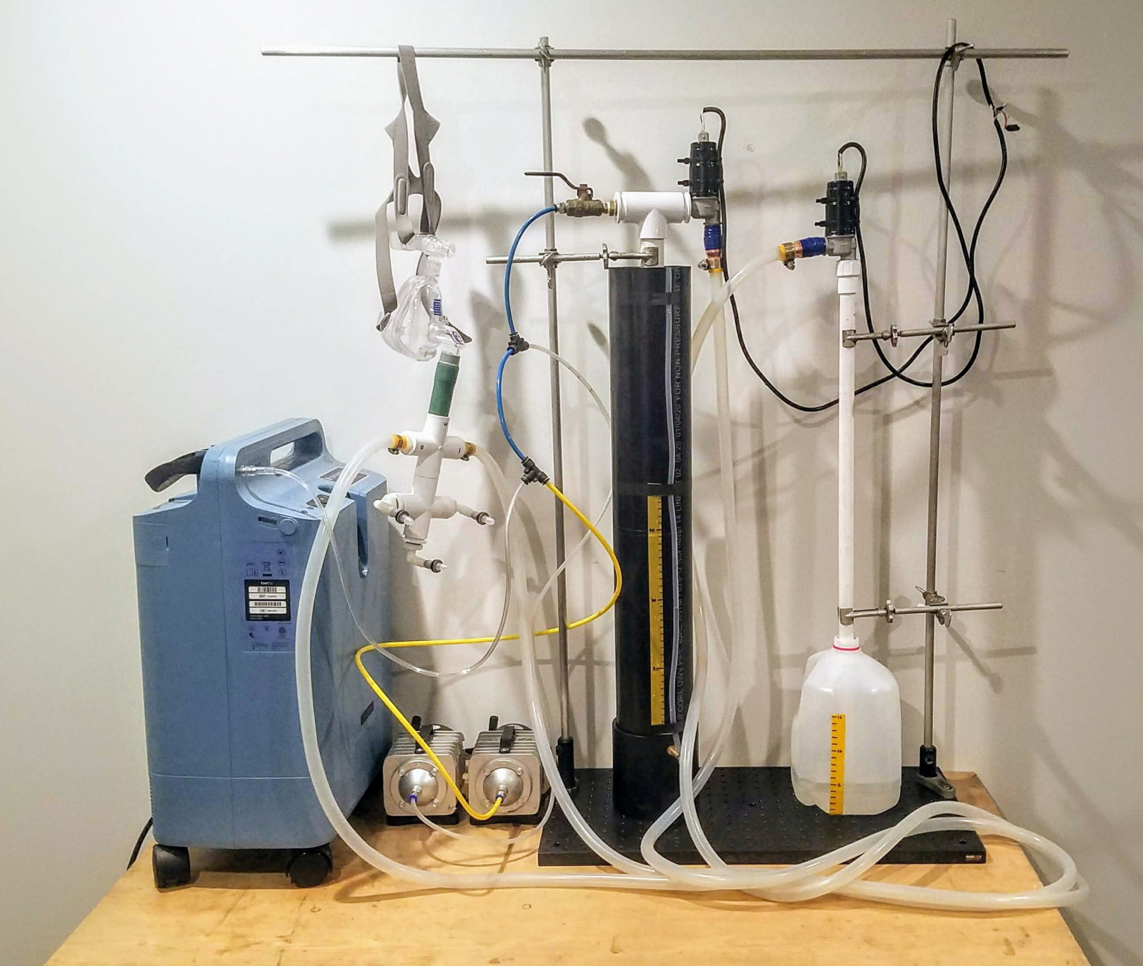
 When viewed from this exact orientation, the right-most pin opens the valve, the left-most pin closes the valve, and the middle pin is +12V power. We chose to use "green means go" and "white shuts tight" for our coloring scheme.
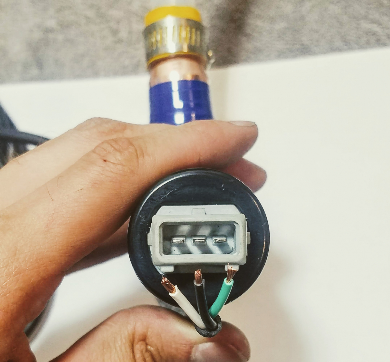 There are multiple ways to accomplish this connection. If you have the proper connector for the valves, ("Bosch 3 pin connector", or "Tyco Electronics Junior Power connector") you can use that, but we did not have these, so we opted to use 2.8mm female spade connectors to connect our three wires. Since we did not have the proper crimping tool, we soldered our wires into the spade connectors and used heat shrink tubing to protect the connectors from touching each other when installed.
 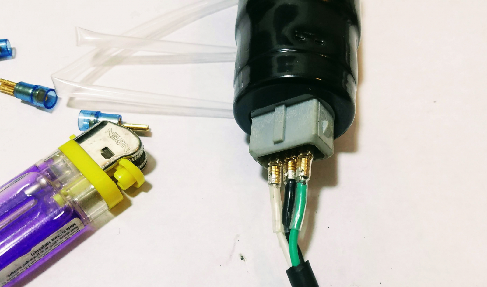 If you don't have these either, you can solder wires directly to the pins of the valve if you have a good soldering iron like a Metcal, Weller, or OKI iron. It might be harder to do this if you have a cheaper iron, so be patient if this is the case. Be sure to use rosin core electrical solder, and not plumbing solder, or you won't be successful. You might also find it easier if you first cover the pins and wire ends in solder before trying to attach them together, like I have done here.
 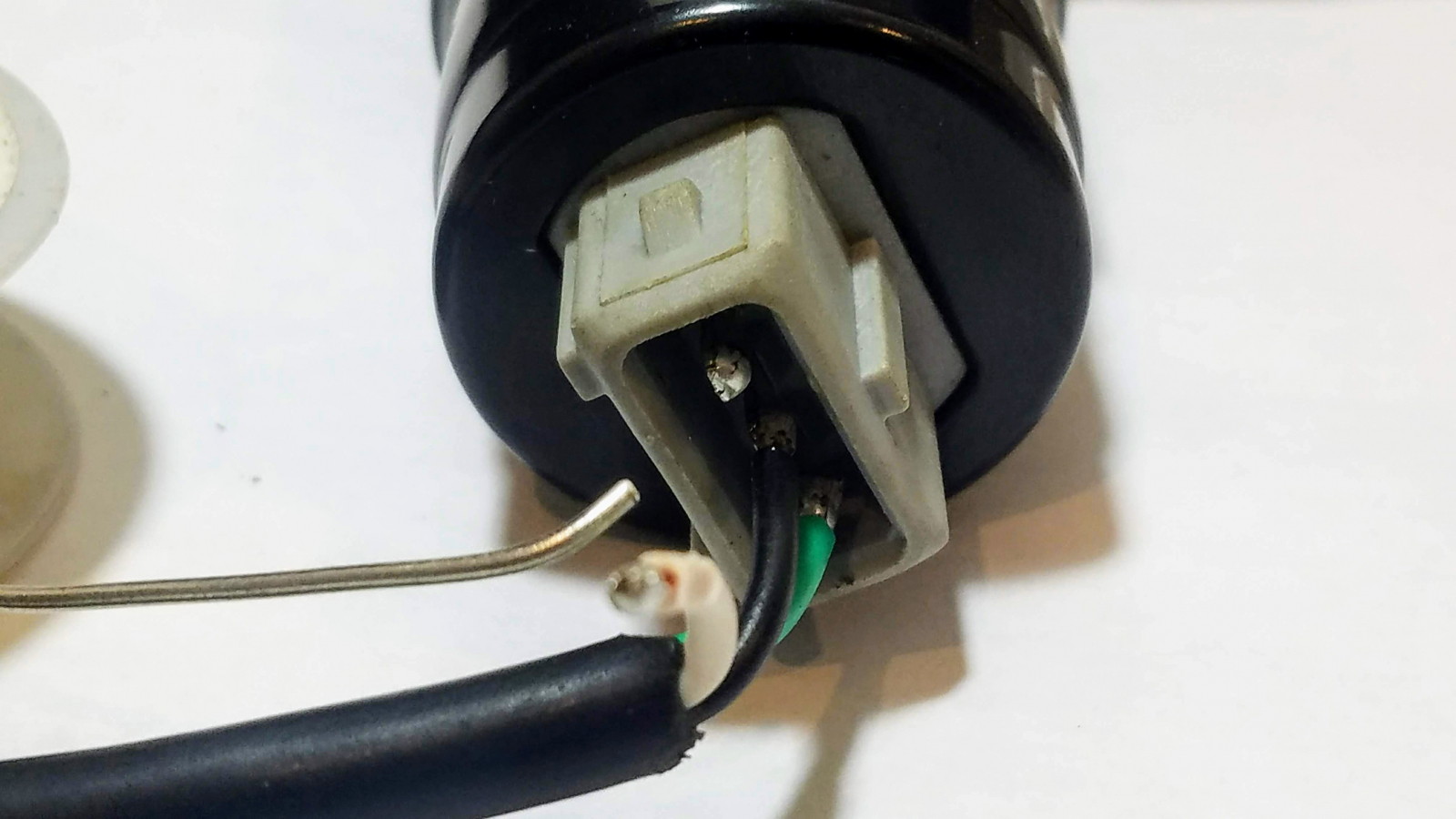 After the wires are attached, use cable ties to affix them in place so you don't accidentally break the connections by moving them around too much.
 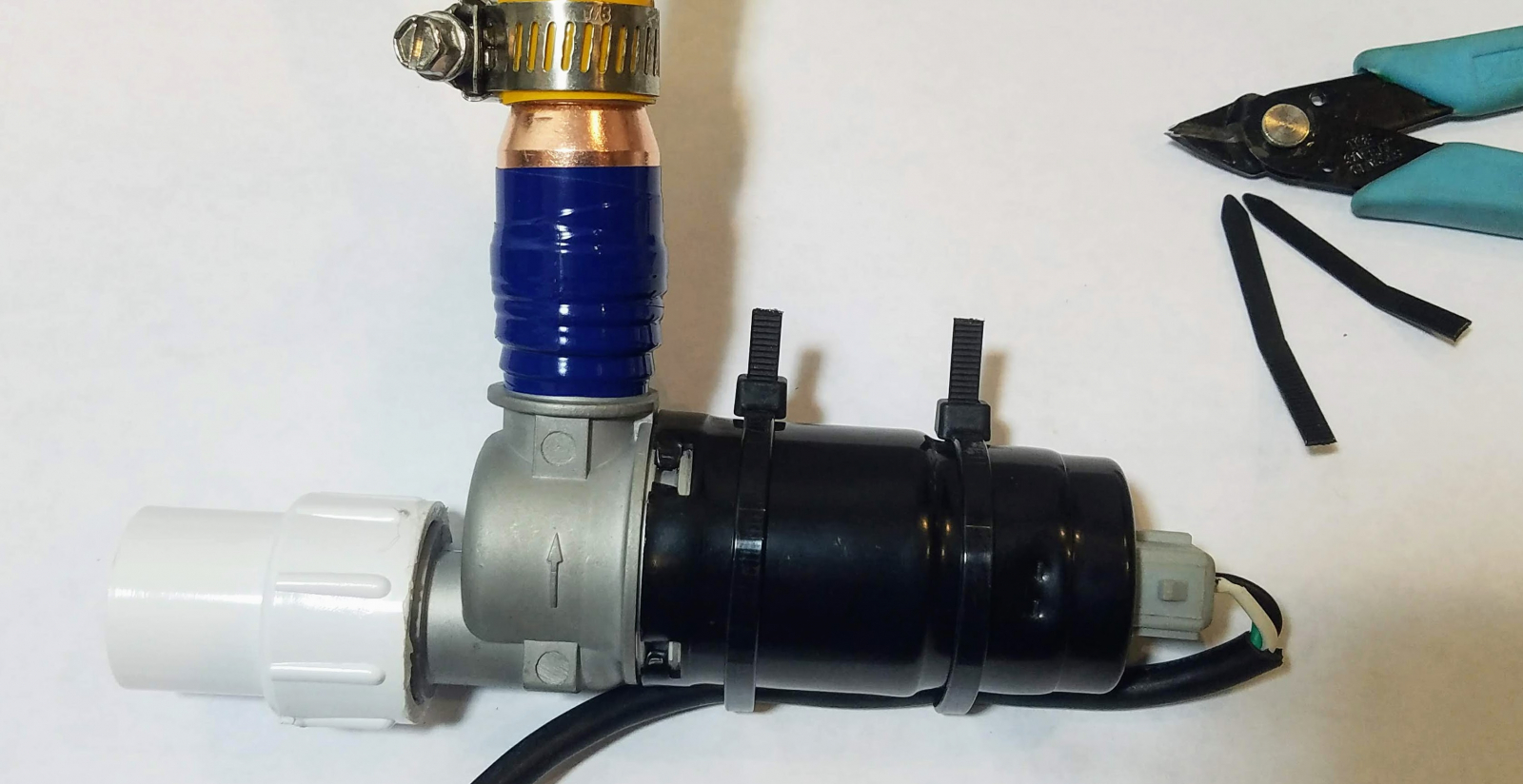 Do this for both valves, and then cut the computer cable in half. This will give you two equal lengths of wire that you will be able to later connect to the circuit board. Then, remove the insulation from the ends of the wires and add a little bit of solder so that the strands don't fray.
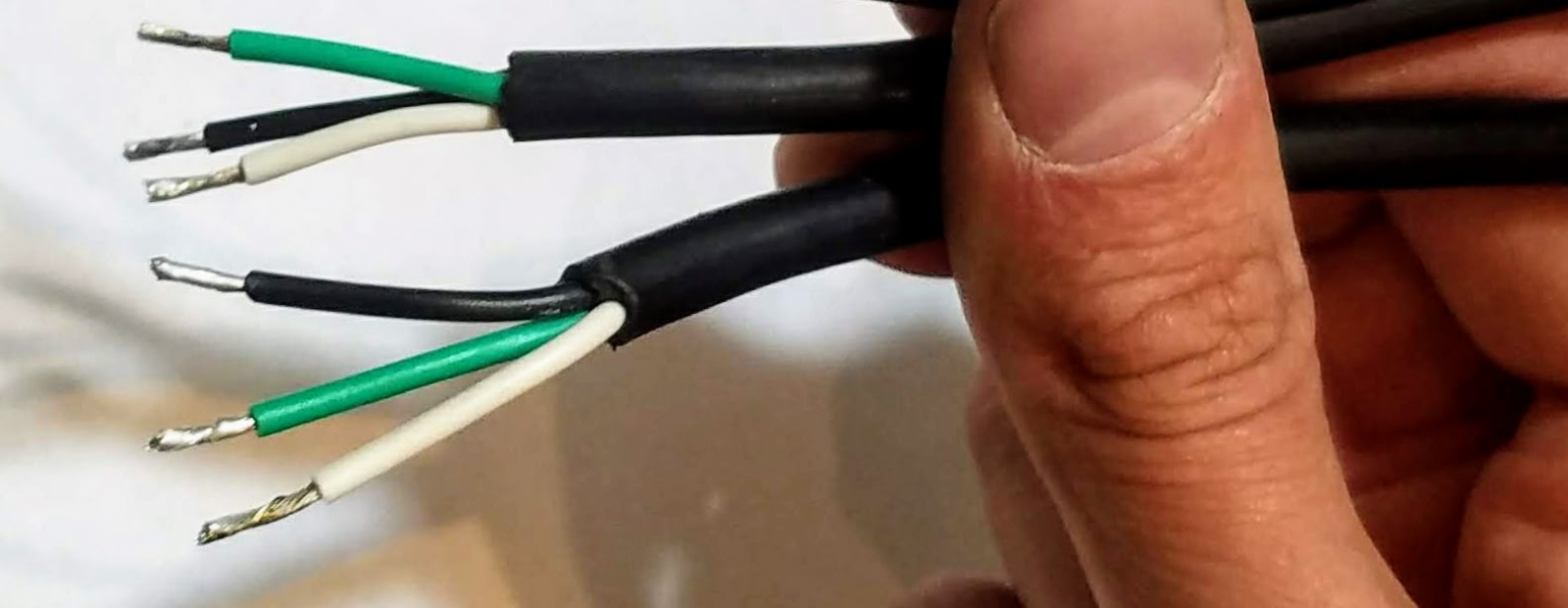
 Help Wanted:If you are a manufacturer who would like to design, produce and distribute a surface-mount version of this circuit board people can just buy ready-made instead, please reach out to us.
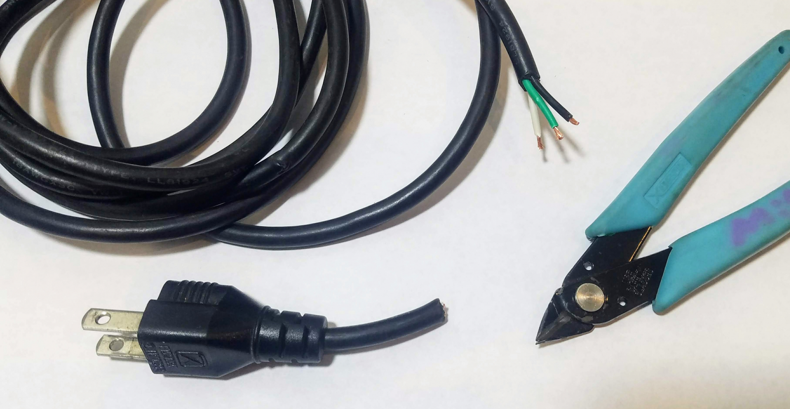
 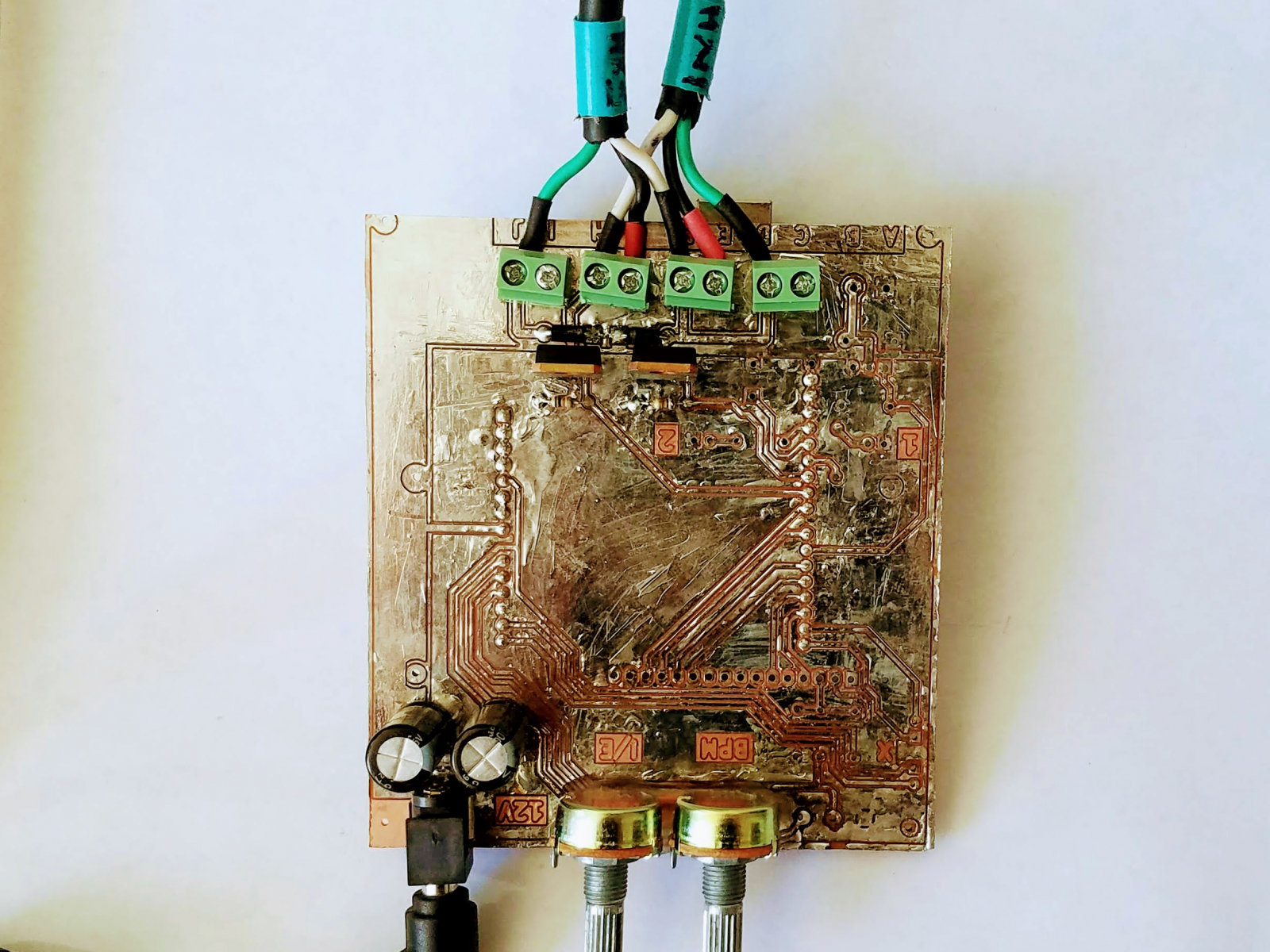 After the wires are installed, power the circuit board with 12VDC through the barrel jack. The adapter should be capable of more than 3A, with a 5.2mm, center positive barrel connector. These are very common adapters used to power things like wi-fi modems. After powering up, the board should immediately turn on and your valves should start working.
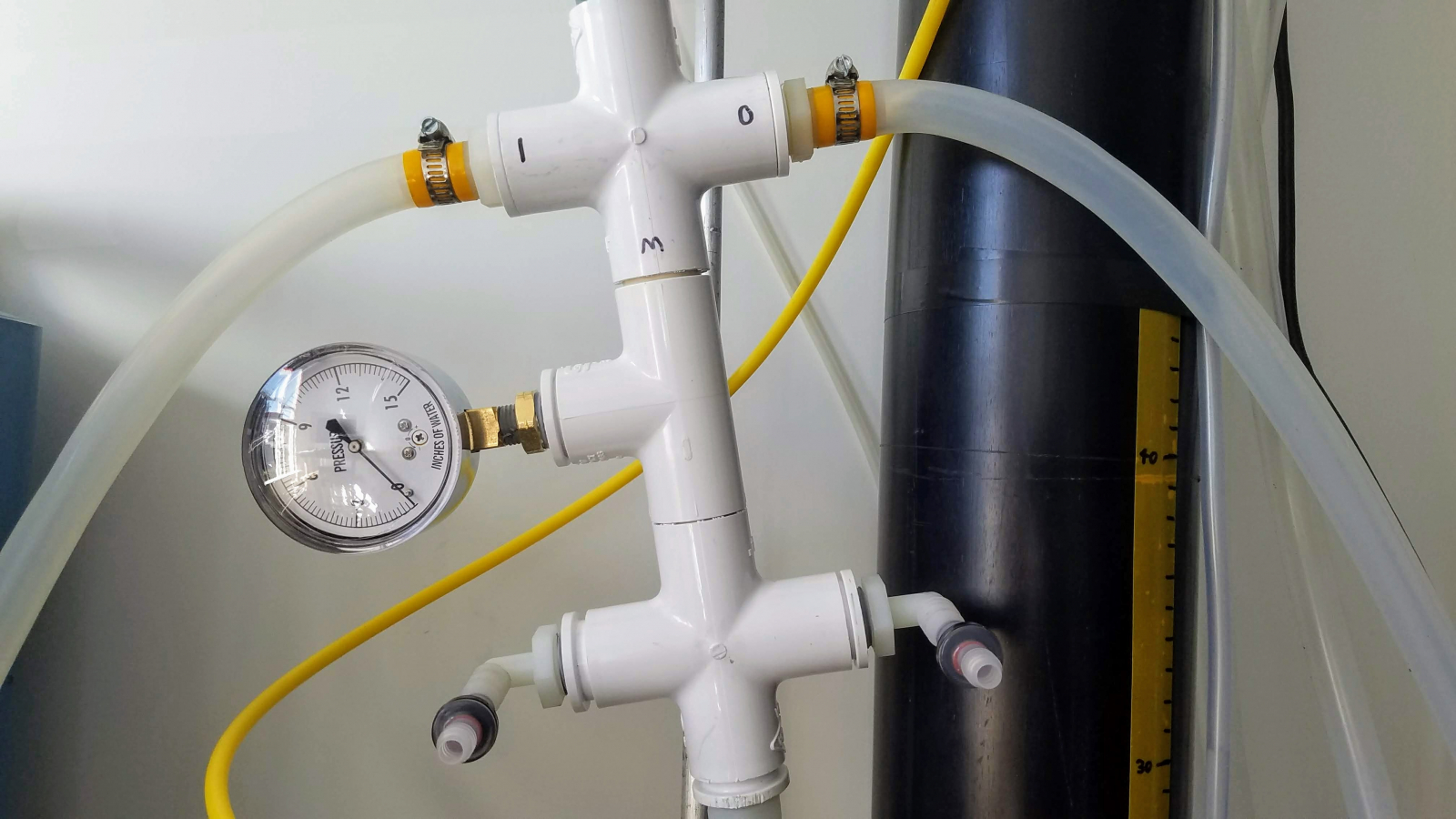
Ventilator Overview and Terminology
A ventilator must accomplish a number of tasks:- It must measure a volume of air (Tidal Volume).
- It must then deliver this air to the patient at a configurable pressure, known as the "Peak Inflation Pressure" or PIP.
- It must then allow the lungs to deflate, not to zero, but to a minimum configurable pressure known as the "Positive-End-Expiratory-Pressure" or PEEP.
- It must humidify incoming air.
- It must allow the patient to breathe in without obstruction if they have the capacity to do so.
- It must do this continuously for weeks without making mistakes.
- It must under no circumstances, ever fail in such a way as to provide more than PIP pressure to the lungs. Otherwise, the lungs can be irreparably damaged.
- The inhale-to-exhale ratio (I/E) must be configurable.
- The number of breath cycles per minute (BPM) must be configurable.
- It must be able to accept air and oxygen from sources that may be substantially in excess of PIP pressure.
Considerations in Our Solution
With these constraints in mind we designed our ventilator such that:- PIP, PEEP, I/E, BPM and Tidal Volume are configurable.
- It is capable of accepting a wide variety of air pressures, including what is available from hospitals, machine shops, and free-piston aquarium air compressors.
- It self-regulates the air pressure and tidal volume, and is not able to create a condition which could dangerously over-fill the lungs.
- It can help humidify the incoming air.
- It can sterilize the outgoing air.
- Allows the patient to breathe themselves if they are able.
- Since no air ever recirculates through pipes in the system, pathogens can't flow backward into the inhalation chamber or compressor.
- It can be disassembled, cleaned, and re-used if further sanitation is deemed necessary.
- It can be made entirely with off-the-shelf parts and with minimal tools.
System Overview
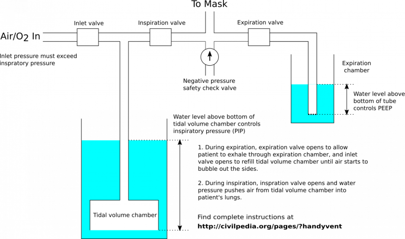
The ventilator consists of two fluid chambers; the inhalation chamber, and the exhalation chamber. The Tidal Volume, PIP and PEEP are configured by the geometry of these chambers. These chambers are connected in sequence with electronic valves, whose timings set the I/E and BPM of the ventilator and control the stages of operation.- Air and oxygen are let into the inhalation chamber through the inlet valve until the chamber is full. When the chamber is full, excess air is vented through bubbles which over-flow the chamber.
- The inspiration valve opens which delivers air to the patient. The PIP pressure is set by the depth of fluid in the inhalation chamber, and can never exceed the water pressure depth. When fluid fills the tidal volume chamber, the air is forced into the patient's lungs until no more air can be displaced.
- The inspiration valve is then closed, and the expiration valve opens. The air will escape into the exhalation chamber, which has a fluid with a depth that sets the PEEP pressure. The exhalation chamber may be filled with caustic or peroxide solution to help sterilize exhaled air.
- While the expiration valve is closed, the inhalation chamber is re-filled. The cycle then repeats.
Required Tools
A few tools are needed to build the ventilator. They are, in no particular order:- A power drill and drill bits.
- Screws and screw drivers.
- Shears or scissors.
- A hand saw.
- Wire cutters.
- A soldering iron and solder.
- Measuring tape.
Inhalation Chamber
For the inhalation chamber, you will need the following plastic pipe pieces:- A 70 cm section of 2" PVC pipe.
- A 2" PVC pipe to 1, 1/2" reducer.
- A 1, 1/2" to 1" PVC reducer.
- A 75cm section of 4 inch ABS or PVC pipe.
- A 10cm section of 1" PVC pipe.
- PVC cement.
- A 1/4" internal-diameter (I.D.) vinyl hose.
- A 1/4" MIP brass hose barb for your hose.
- Light colored vinyl tape.
- Dark colored vinyl tape.
- A means to cap-off the bottom of the 4" pipe (pictured below). For this we used a 4" PVC coupling, a 4" female threaded adapter, and a 4" plug, which was the only means available from our local plumbing store. However, if you have a boring-old cap then this could work too, but it may be harder to clean the vessel with the end permanently closed.
- A powered drill.
- A saw to cut the pipes to the correct length.
- A 3/8" drill bit.
- An adjustable wrench.
- A permanent marker.
Exhalation Chamber
The exhalation chamber operates on a similar principle to the inhalation chamber, where fluid of a particular depth sets the working pressure. It does not need to be as large as the inhalation chamber, and can be made from easy-to-get parts as well. You will need:- A 1 gallon plastic milk carton.
- 75 centimeters of 1/2" PVC pipe.
- A permanent marker.
- Light-colored vinyl electrical tape.
Negative Pressure Check Valve
In case the patient needs to inhale air while the inspiration valve is closed, we must fabricate a negative pressure check valve to install next to the mask. This valve must have a high flow rate and be capable of actuation with minimal pressure. Most check valves are not suitable, as the pressure required to allow flow through them is too high to inhale.We have found that silicone duck bill valves work at a low enough pressure to be satisfactory. They are sold a very many places online and at auto parts stores, advertised along the lines of "enema check valve", "fuel check valve", "10mm check valve", "silicone check valve", or similar.- A 3/4" PVC Cross.
- Three 3/4" PVC to 1/2" FIP bushings.
- Three 1/2" MIP to 3/8" hose barb bushings, straight or right-angle are both O.K.
- Three 5cm sections of 3/8" I.D. tubing, vinyl, rubber or silicone are all acceptable.
- Three duck-bill check valves.
- A 5cm length of 3/4" PVC pipe.
- Thread sealing tape.
- An adjustable wrench large enough for the hose barbs.
- A saw to cut the PVC pipe to the 5cm length.
- Scissors for the small tubing.
Mask Port
The mask port is where the ventilator's pipework meets to create an inlet/outlet port for the ventilator mask or tubing. In this design, it also provides a port for the negative pressure check valve to allow the patient to breathe in if necessary.To build it, you will need:- A 3/4" PVC cross.
- Two 1/2" FIP to 1/2" hose barbs.
- Two 3/4" PVC to 1/2" MIP bushings.
- Thread sealing tape.
- Your check valve you made previously (not pictured).
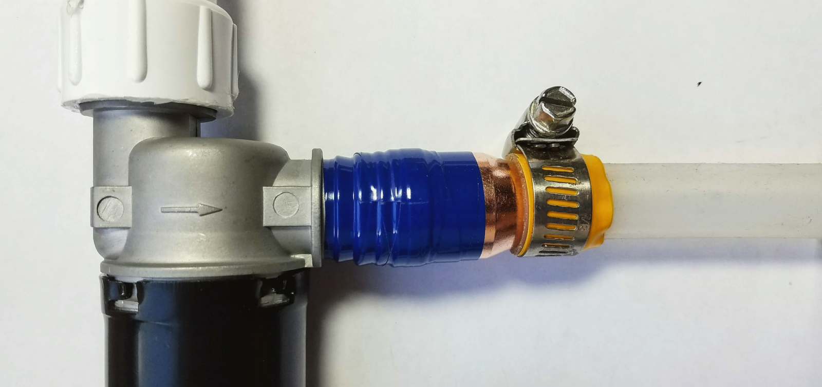
Exhalation Valve
The exhalation valve opens to allow air escape from the lungs to the PEEP chamber. It must have very large opening and fast actuation to allow the air to escape quickly enough, which as we found is a hard-to-find combination when searching for electric valves. We tried 5 different types of valve before settling on idle air intake valves, the sort used to control the airflow to a gasoline engine. They proved to be the most cost effective, reliable and easy-to-get valve available. They leak a little bit of air when closed, which at first we thought might be a disadvantage, but turned out to be very beneficial for reducing air-hammer and keeping the ventilator very comfortable to use. However, this substantially increases the air requirements and we are actively looking for better valves.To build the exhalation valve, you will need:- A BMW idle air intake valve, part number 13411286065 or something equivalent. These valves are cheap and readily available from hundreds of vendors.
- A 3/4" to 1/2" copper reducer.
- Vinyl tape.
- Thread sealing tape.
- A 3/4" FIP to 1/2" PVC adapter.
Inhalation Valve
The inhalation valve is built very similarly, however instead of a 1/2" PVC bushing, you instead must use a 1" PVC bushing. You'll need in total:- A BMW idle air intake valve, part number 13411286065 or something equivalent.
- A 3/4" to 1/2" copper reducer.
- Vinyl tape.
- Thread sealing tape.
- A 3/4" FIP to 1" PVC adapter.
- A 1" PVC tee
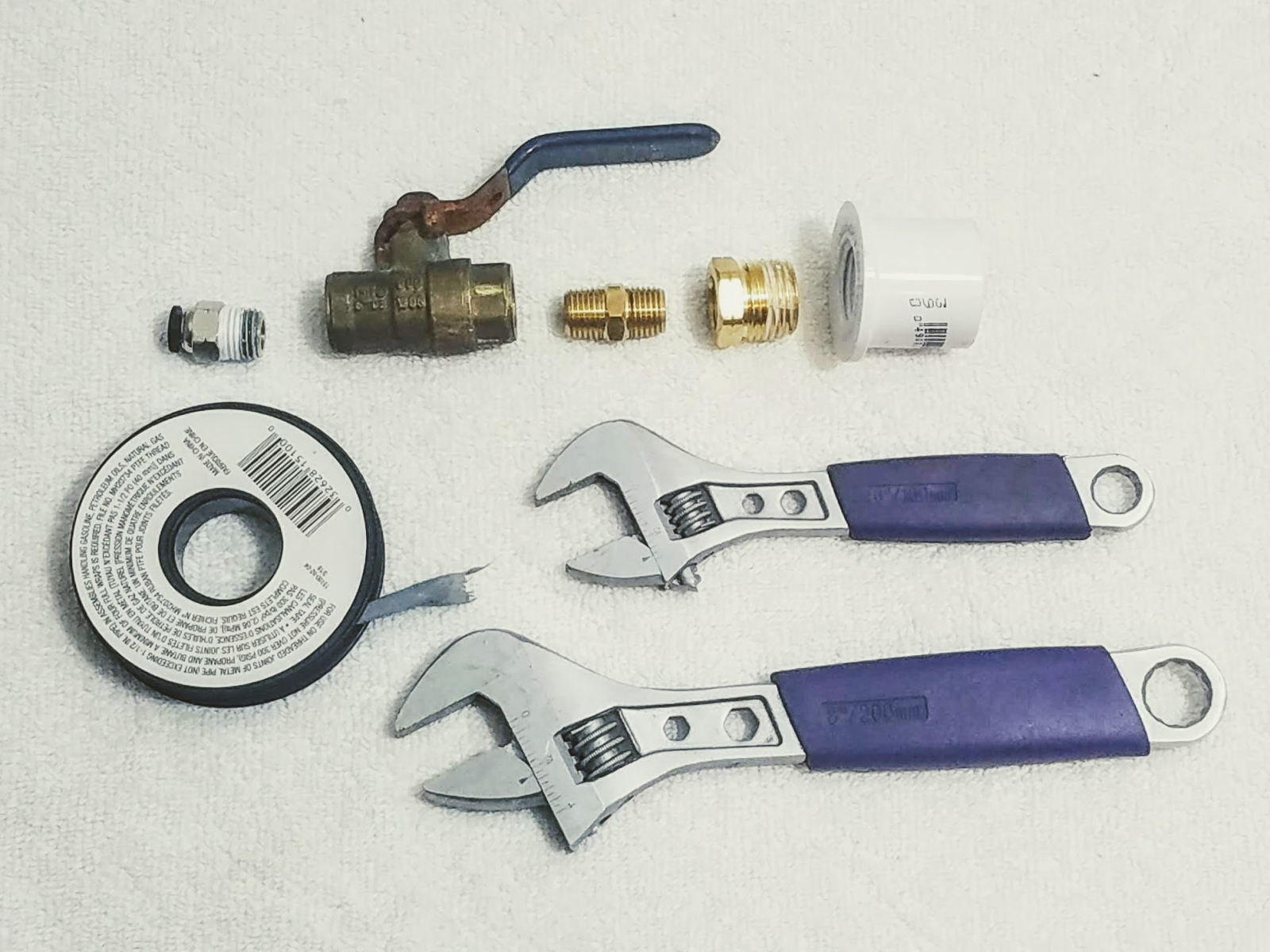
Inlet Valve
The inlet valve is an adjustable ball valve which is used to control the flow to the PIP chamber. We at first tried using an electronic valve, but it proved to be an unnecessary complication and a ball valve was sufficient instead. The purpose of this valve is to allow the operator to minimize the overflow bubbling on the PIP chamber. In the case that the lungs are not using as much air as the compressor can provide, it should be partially closed such that there is only some bubbling in the PIP chamber during the exhalation, but not an excessive amount. There will always be some pressure, and bubbling in the PEEP chamber since the electronic valves always allow a little air to leak through them. To build the inlet valve, you will need:- A 1/4" ball valve with handle.
- A 1/2" FIP to 1" PVC bushing.
- A press-fit air inlet that accepts a 1/4" O.D. air hose, like the sort used for pneumatics.
- Brass fittings to adapt your ball valve to the PVC bushing and quick-connect air inlet.
- PTFE thread sealing tape.
- Adjustable wrenches.
Air Pipework
We now need to connect the patient tee to the valves. To do so, we used 1/2" inner diameter silicone hose, as we found that rubber and vinyl hose smelled too much for a comfortable experience. Unfortunately, the silicone hose we chose (11/32" wall thickness) is very soft and easy to kink, so it strongly recommended[/b] to instead use something with a thicker wall.You will need:- Two 6 to 10 foot sections of silicone or flexible plastic hose with a 1/2" inner diameter.
- Four stainless steel hose clamps.
- Vinyl tape.
- A permanent marker.
- Scissors to cut the hose.
- A screwdriver to tighten the clamps.
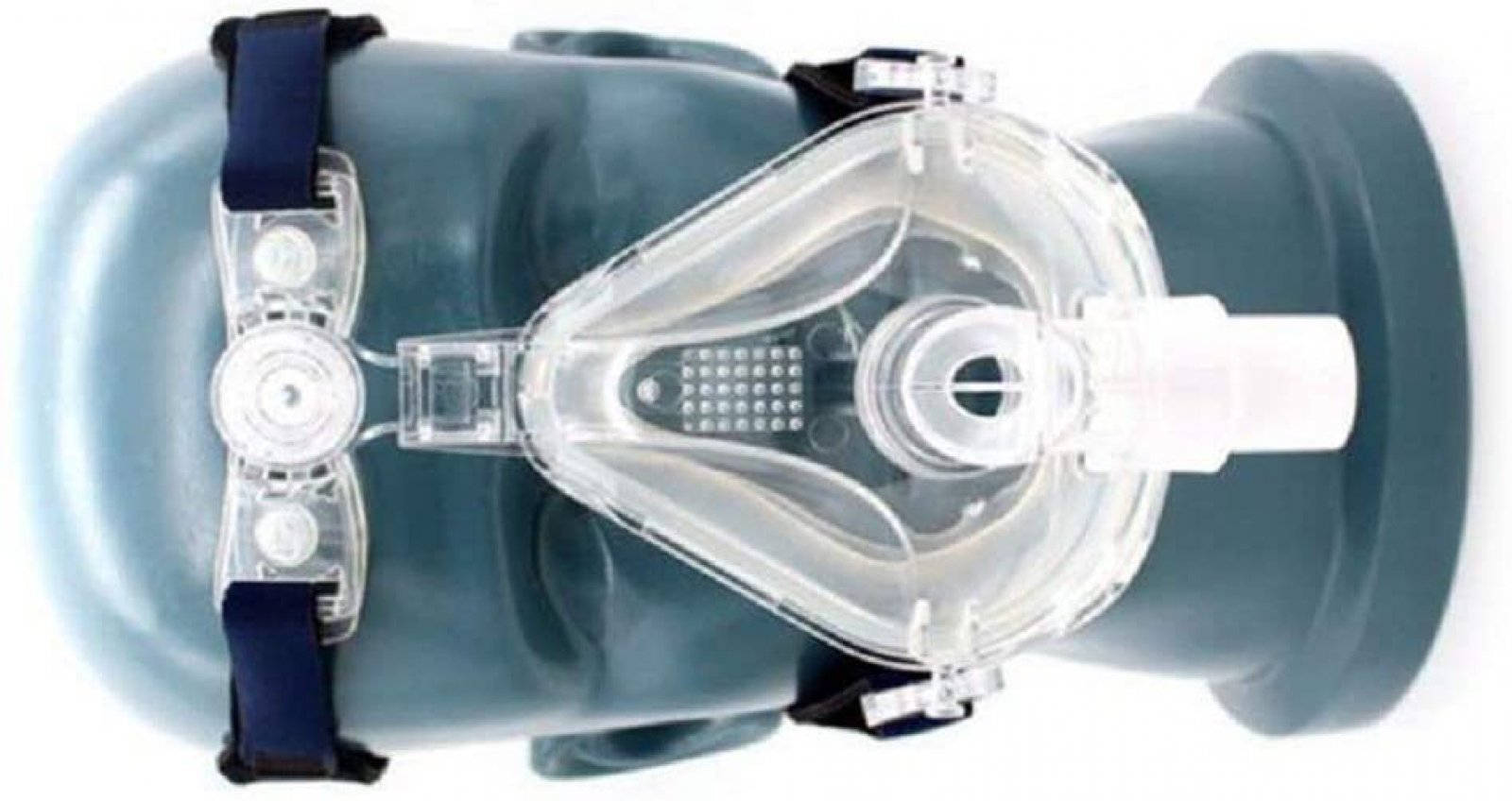
Air Mask
The needs of the patient will determine what kind of mask should be used. However, for demonstration purposes, we have found that a full-face CPAP mask can be repurposed as a ventilator mask with minimal modifications. To build the air mask, you will need:- A full-face CPAP mask.
- 12cm of 3/4", dual-wall silicone heater hose.
- Vinyl tape (not pictured).
- Scissors for cutting the hose and tape.
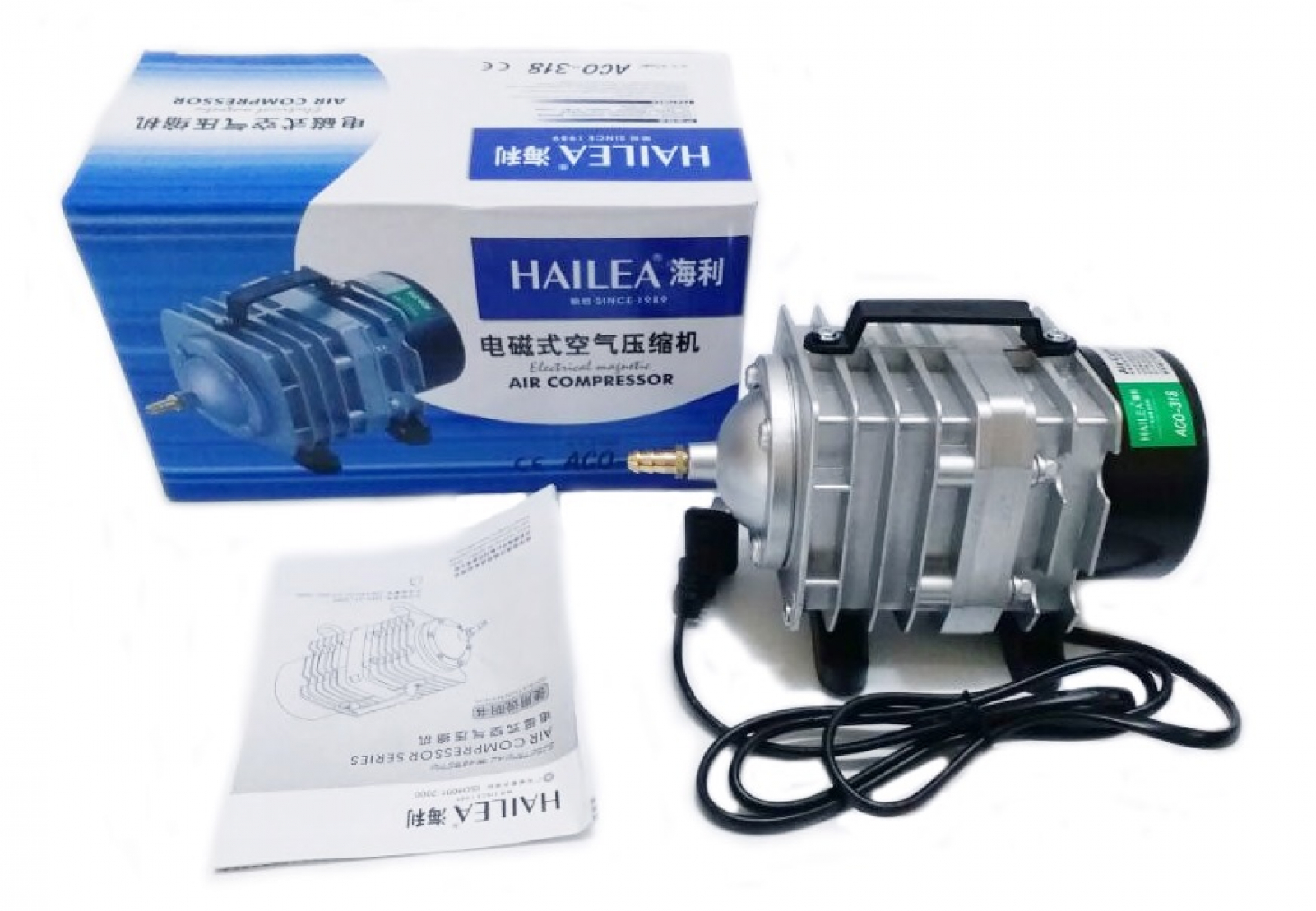
Air Compressor
The air compressor must be capable of providing a pressure in excess of the PIP pressure, with enough flow to fill the lungs and account for leakage the valves might have. Our recommendation is that your compressor or blower is[/b] capable of delivering at least 200LPM at 1PSI[/b].We found that a good compressors for the job are the aluminum-body ones sold as "hydroponic compressors", which are free piston compressors. This means they are big diaphragm pumps, which have no motor, gears, or any special seals which could wear out, and no oils which could contaminate the outgoing air. We have used these compressors, particularly the ones made by the Chinese company Hailea for more than 10 years in machine equipment without any failures, so their design is very admirable.Final Pipework
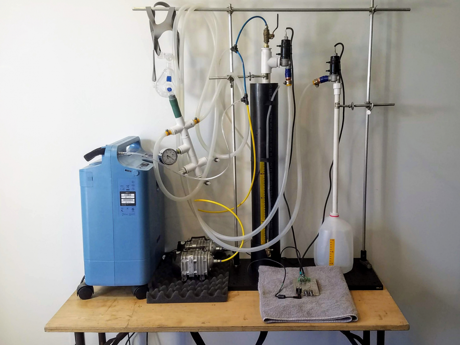
The final assembly should look something like this fixture pictured here. The inlet chamber and exhalation chamber don't need to be next to each other, but it is important that they are secured upright and cannot fall over. It is important also, that the inner pipework of the inhalation chamber cannot float out of position.Electrical Cable Assembly
The type of valve we chose (part number) has three electrical connections: one +12V connection, and two other 0V connections, which either open or close the valve depending on which one is engaged. We must connect three wires to these connections that will be later plumbed into the control circuit board. For this you will need:- 3-conductor stranded wire, an IEC computer cable will do.
- Solder and a soldering iron, or 2.8mm female spade connectors and crimping tool. Be aware, that normal 5mm spade connectors are too big to fit!
- Heat shrink tubing and a cigarette lighter.
- Cable ("zip") ties.
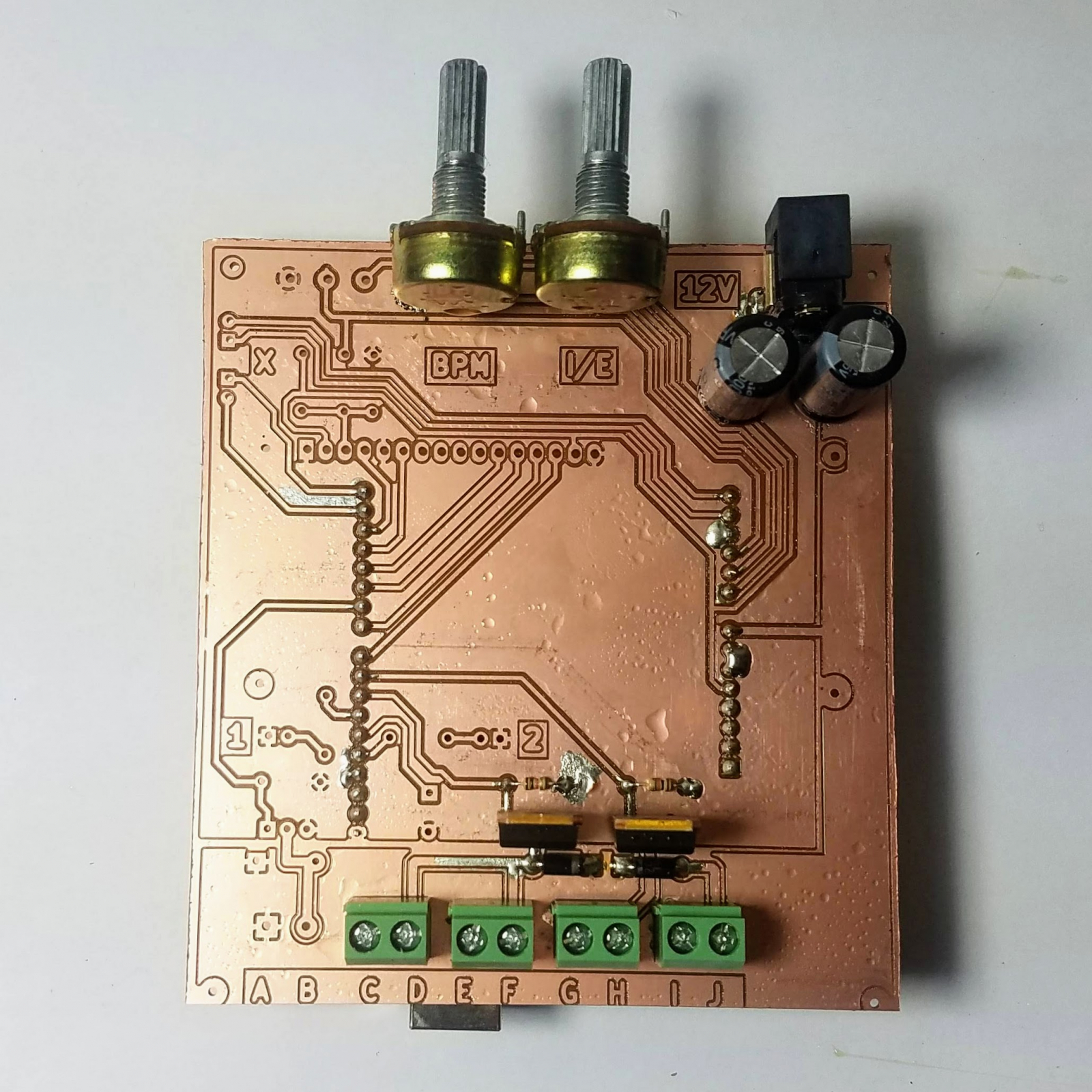
Circuit Board
To fabricate the circuit board, send the Gerber files to any PCB manufacturer and they should be able to provide you with the printed board. Then, solder the components listed in the bill of materials, into the holes of the circuit board and upload the code to the Arduino. An experienced maker, hacker or electrical engineer should be able to very easily handle this process. We have a separate page on how to build the circuit board, which you can find here.Wiring up the Circuit Board
You will need to wire the valves to the terminals on the circuit board like so:- Connect the +12v (black) wire of the inspiration valve to "E"
- Connect the +12v (black) wire of the expiration valve to "G"
- Connect the OPEN (green) wire of the inspiration valve to "D"
- Connect the CLOSE (white) wire of the inspiration valve to "H"
- Connect the OPEN (green) wire of the expiration valve to "J"
- Connect the CLOSE (white) wire of the expiration valve to "F"
- "A", "B", "C", and "I" are not connected.
Mask Manometer (Optional)
You can optionally create manometer to install at the mask which will give you more accurate pressure readings than your 1cm graduations will suggest. You can build the manometer by combing a low-pressure gauge (ours is 15 inches H2O) with a 3/4" PVC tee that installs between the mask cross, and the negative pressure valve cross. By not using PVC glue, you can keep it removable.Operation
An experienced pulmonologist will understand how to most effectively use this system, but a general overview of its operation is as follows:- Fill the PIP chamber with water to a level which will set the minimum inspiratory pressure. Peak pressure will be about 10cm more than this.
- Fill the PEEP chamber to an acceptable level to set the maximum expiratory pressure.
- Turn on the air compressors and oxygen supply.
- Set BPM and I/E ratio to something suitable for the patient.
- Monitor the PIP manometer to confirm that the ventilator is cycling appropriately.
- Always monitor an %SPO2 meter to ensure that a safe amount of oxygen is being delivered.
Help Wanted
There are several improvements we can still make, and we're looking for help in the following areas.- Building more ventilators!
- Helping compose how-to guides, videos and diagrams.
- Manufacturing a surface-mount control circuit board people can buy ready-to-go.
- Finding large-orifice air valves that leak less.
- Making PEEP adjustable without needing to change the water level.
- Making a pressure monitor that can alarm if the machine stops cycling or the pressure is out-of-bounds.
Donations
If you would like to financially support our development of the HandyVent, you are welcome to support our gofundme campaign here.Final Thoughts
We have used this ventilator on our own lungs while keeping SPO2 at 98%, and are satisfied enough to publish it as a viable and safe design that can be rapidly built all around the world. If you would like to keep informed about this project, please reach out to [email protected] who is our team's current point of contact, or subscribe to this page on civilpedia!License
This project is released under the Creative Commons Attribution, Noncommercial Share-Alike License 4.0, CC BY-NC-SA 4.0. If you would like a commercial license, we can make one available, but on a case-wise basis to ensure you are not selling something that is potentially dangerous.Contributors
Hack the planet!- Adam Munich
- Jake Waters
- John Hiesey
- John Fitz
- Nic Weidinger
- Ian McNanie
- Esther Shang
- Kiki Jewell
- Marc Juul
- Alex Papazoglou
- Austin McChord
- Paul Richard