Building the HandyVent Control PCB
The control PCB for the HandyVent is a simple circuit board made with through-hole components that are easy to solder. This short page will help you understand how to build it. 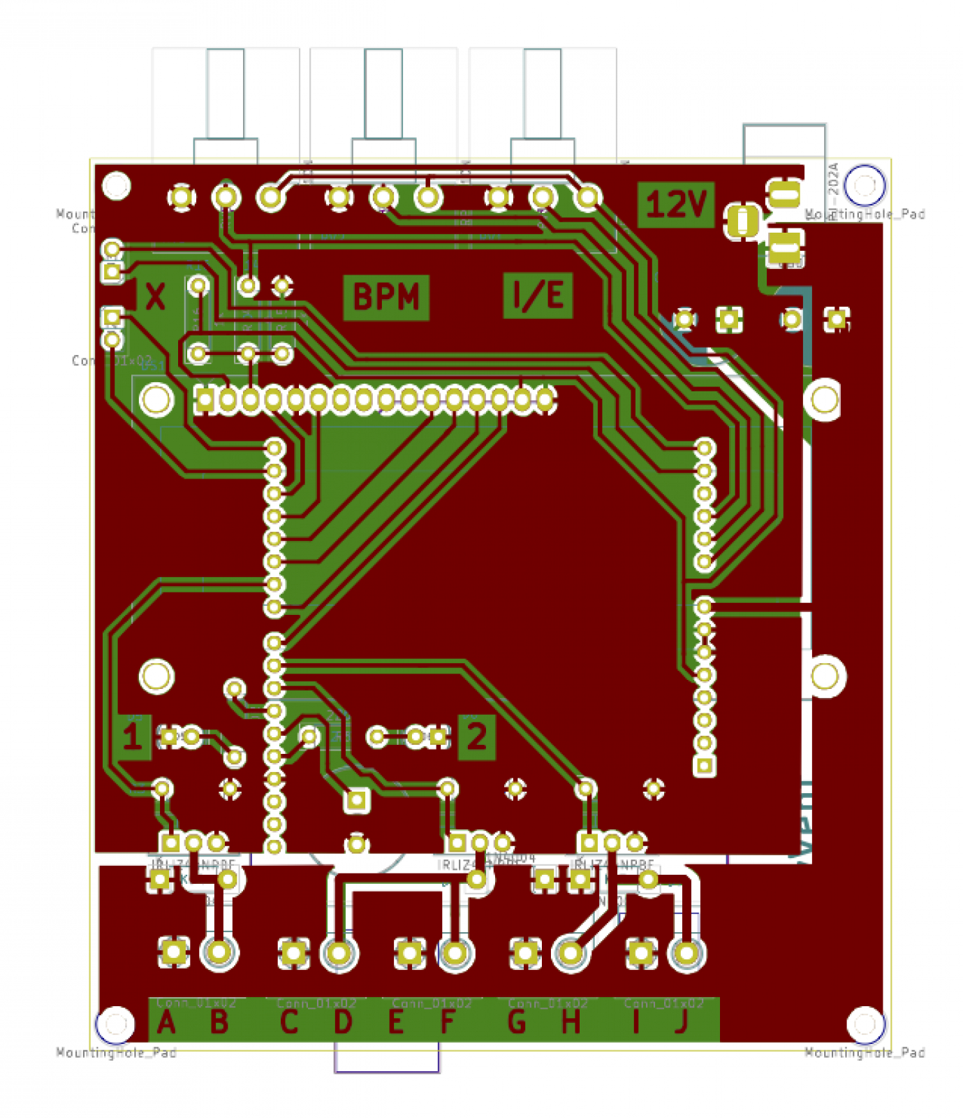
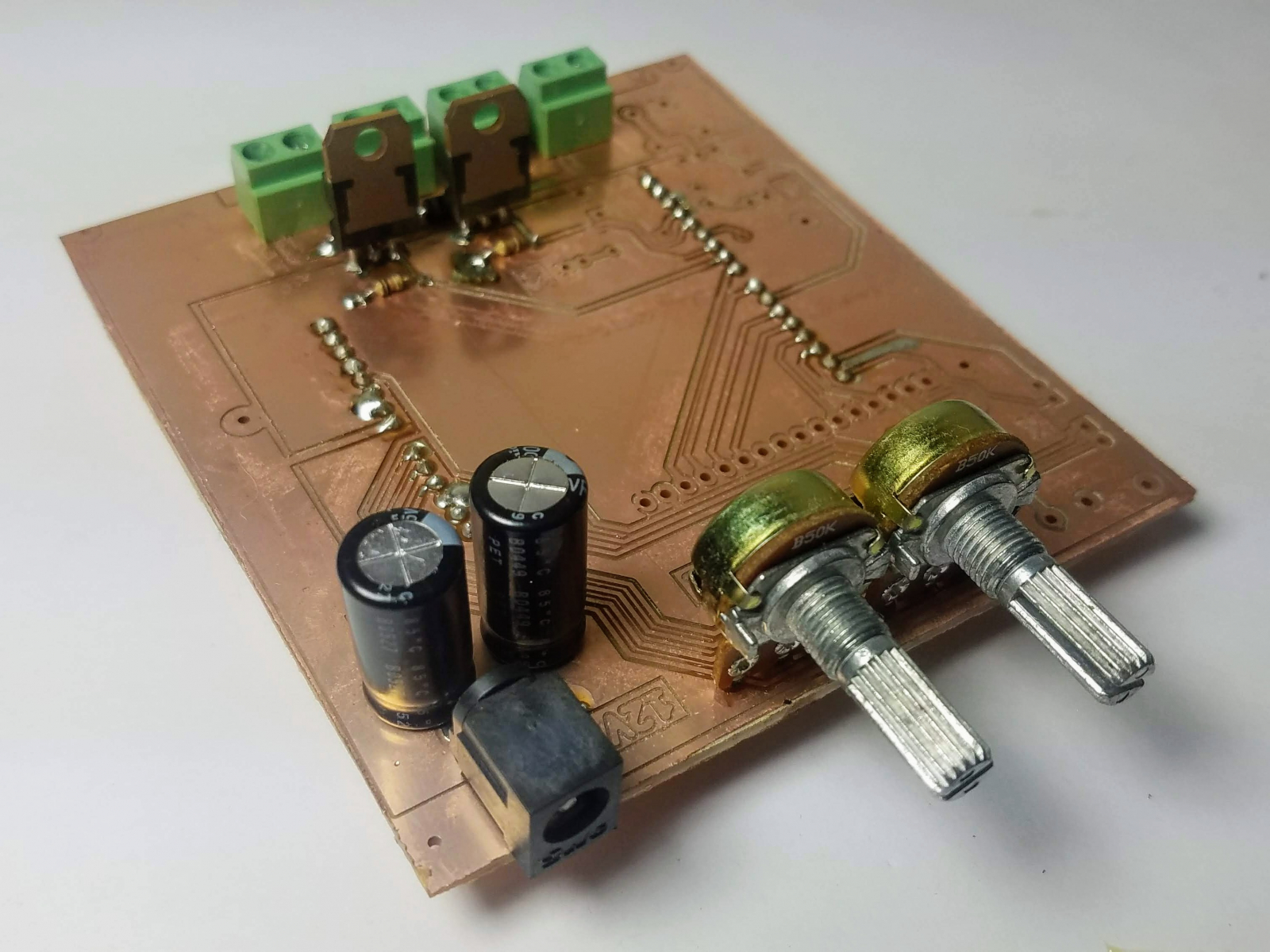
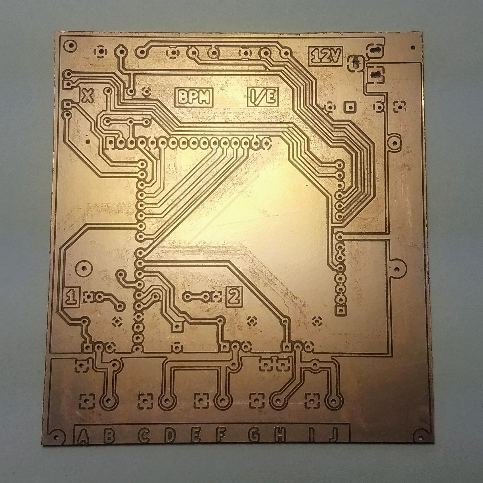 Normally the PCB will be painted green and exposed metal will be covered with gold or silver, but we didn't have the time to have a professional manufacturer build the board, so ours used here will be bare copper. This makes it a little harder to solder, but the result will be similar to a professionally-made board.
 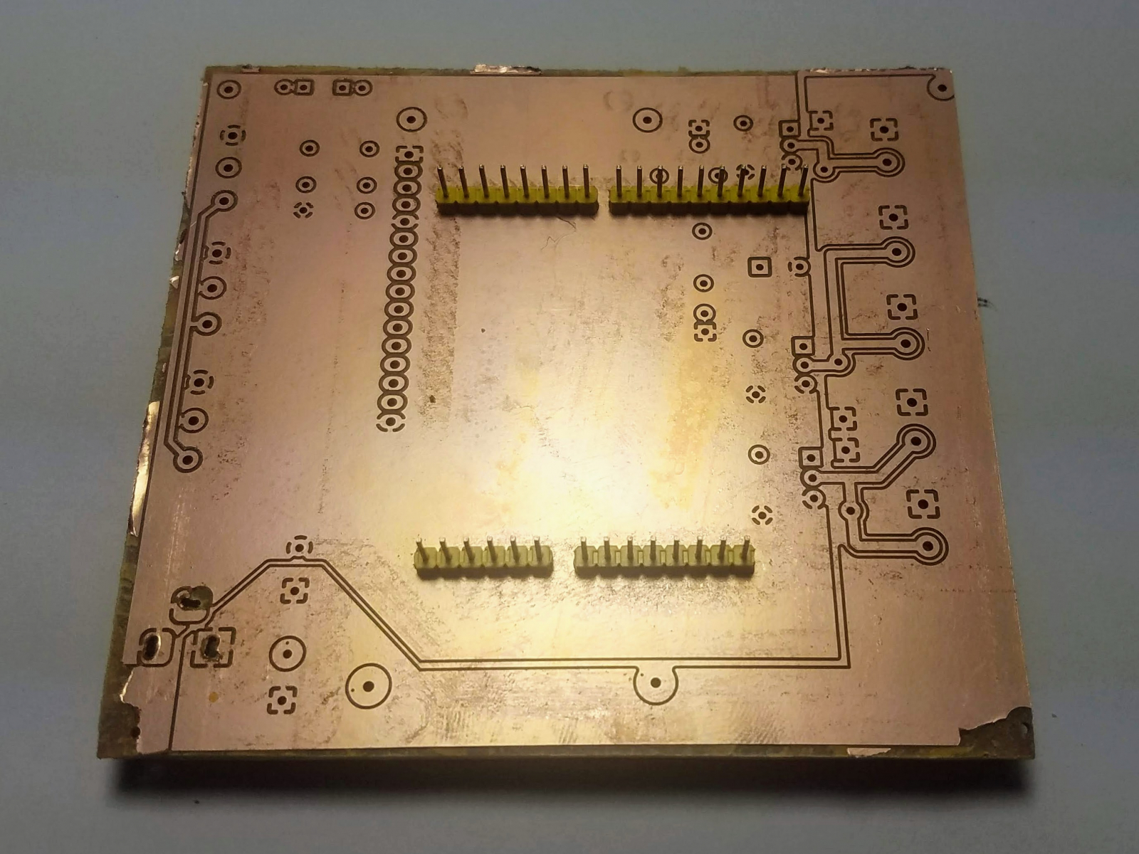 Then, flip over the circuit board so that the top side is visible, and solder the headers into place. Make sure they stay at a right angle (perpendicular to the board) while you are doing this, otherwise they may break if you try to force them later.
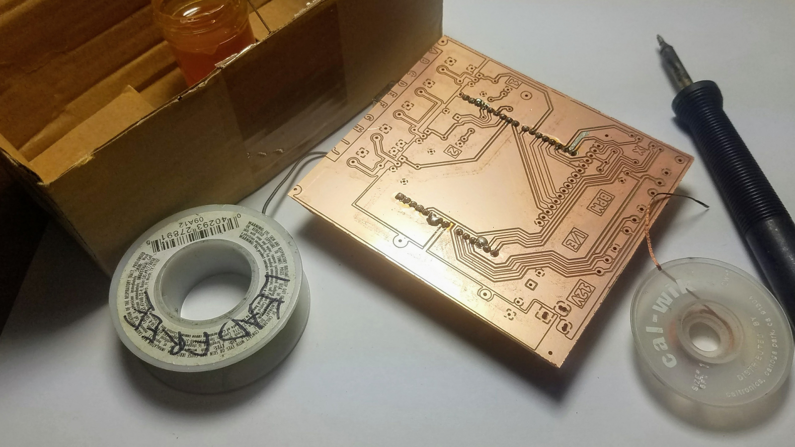
 You might notice there are a lot of missing parts, particularly, and LCD screen, a third transistor, a buzzer and some LEDs. These parts are all optional and can be installed for experimental purposes.
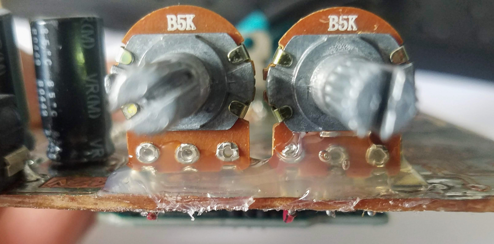
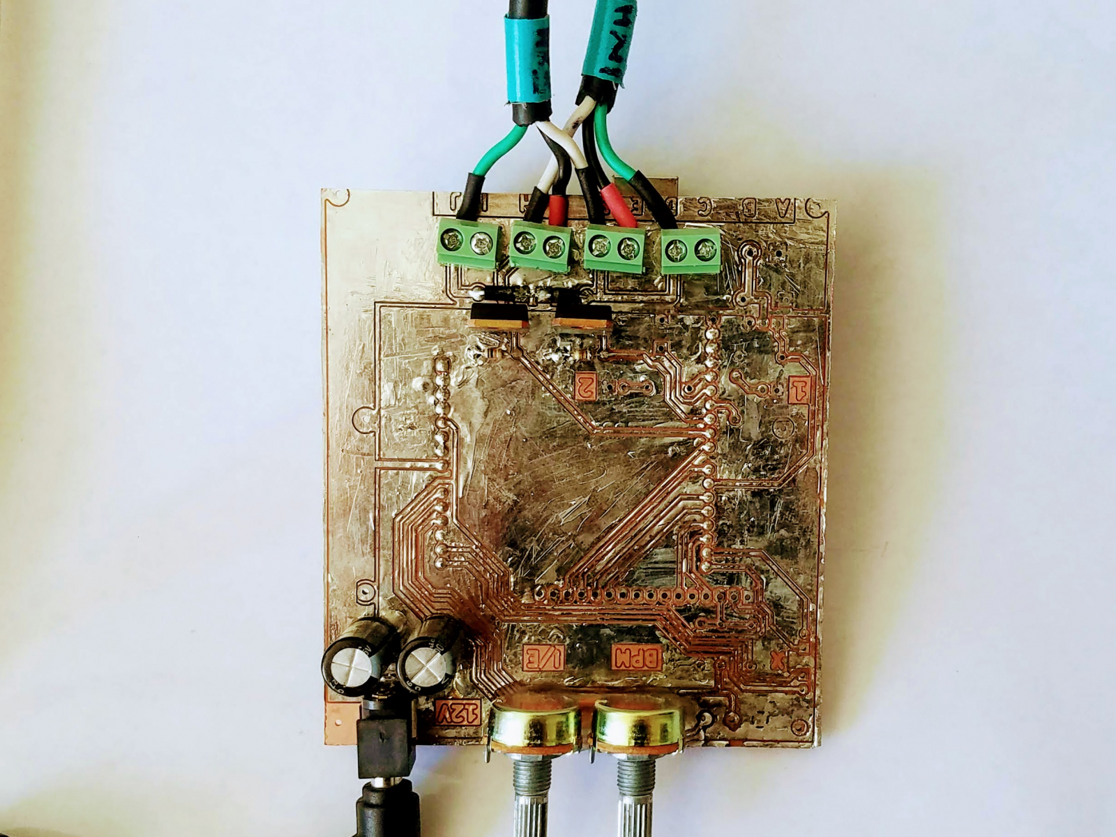 You might notice that our entire board is now covered in solder. We did this to protect the copper from oxidation, however, you don't need to do this if you have a professionally-made circuit board.
Components
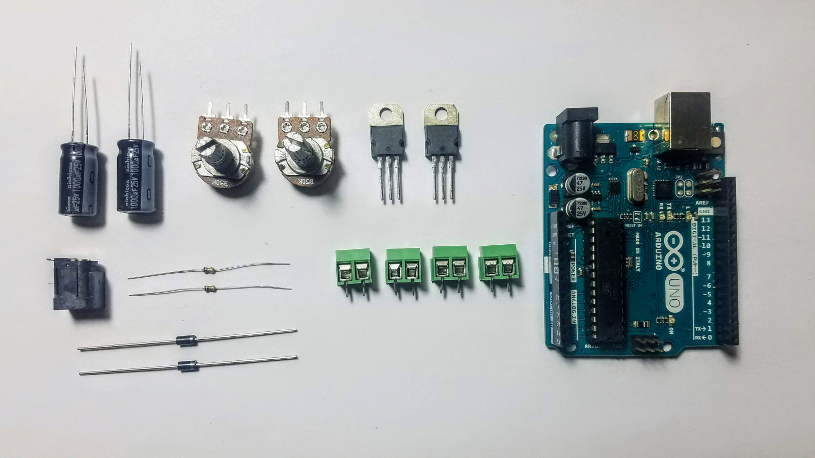
You will need:- An Arduino UNO or equivalent
- Two 1000uF, 25V capacitors
- Two 100V, 1A Schottky diodes
- Two 100V, >30A N-Channel Power MOSFETs
- Two 10k resistors
- A 5.2mm female barrel jack
- Four 5mm spacing wire terminal blocks
- Two medium-size potentiometers, 5k, 10k, or 50k ohms are all usable
- 0.1" Male Breakaway Headers
- Duct tape
Tools
You will need the following tools:- A soldering iron
- Electrical solder and solder flux
- Wire cutters
- Hot glue gun and glue
- Alcohol to clean up afterward
- A USB type A to type B cable for the Arduino UNO
Printed Circuit Board
To fabricate the circuit board, send the Gerber files to any PCB manufacturer and they should be able to provide you with the printed board. The circuit board is an Arduino Uno shield made with hand-soldered components. All of the design files and software are available in this gitlab repository. The circuit board is in ./kicad/small_board_simple/.Solder the headers in place
Take your male breakaway headers and cut them to the appropriate size for the Arduino uno using your wire cutters. Then, install them into the circuit board so that the solder-side is on the top of the board, and the headers are on the under-side.Install the 10K Resistors
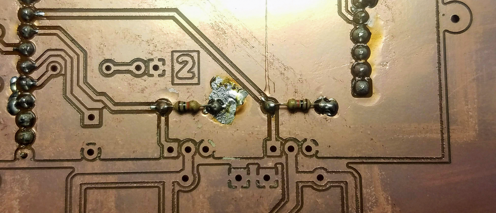
Next, install the two 10K resistors just under the "2" printed on the circuit board. These will make sure the transistors turn off if the power is disconnected. They direction in which the resistors are installed is unimportant- they will work both ways.Install the Schottky Diodes
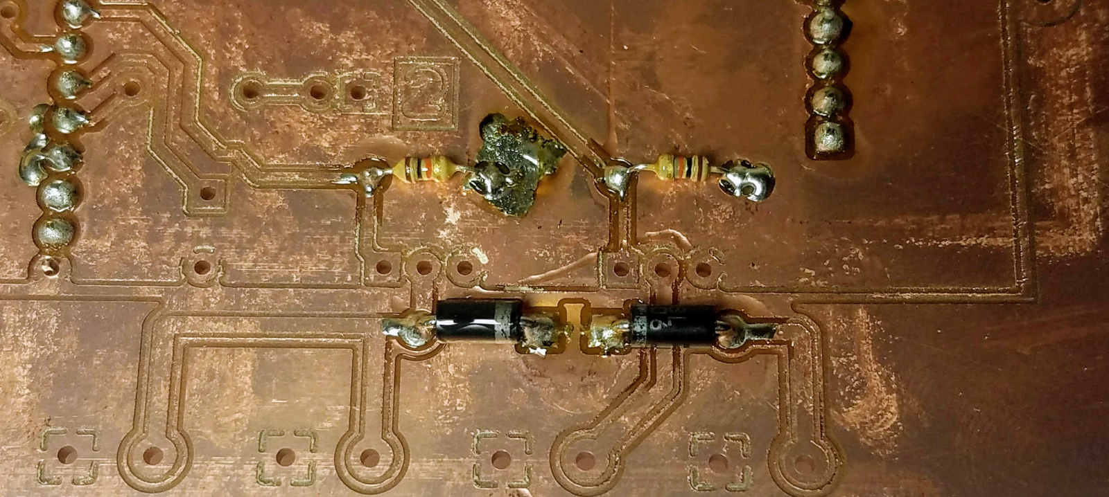
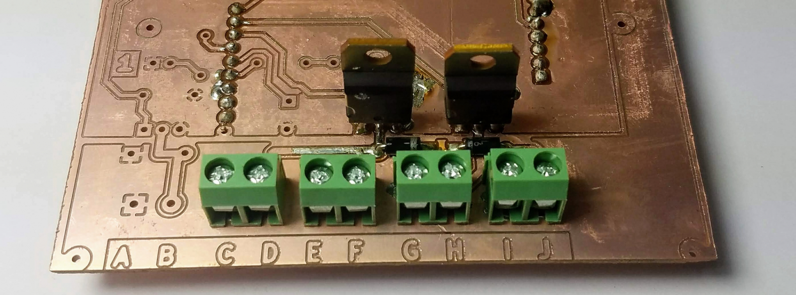
Next, install the Schottky diodes just under the resistors. The direction here is important! You need to make sure that the white stripes on both diodes are facing to toward each-other, or electricity will flow the wrong way and it will explode your transistors!Install the MOSFETs
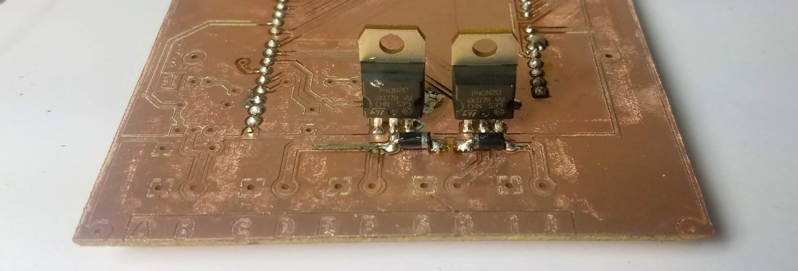
Next, install the Schottky diodes just under the Schottky diodes. The direction here is important! [/b]You need to make sure that the metal tabs stripes on both transistors are facing to toward the Schottky diodes, or electricity will flow the wrong way and your transistors will explode!Install the Wire Terminal Blocks
Install the four wire terminal blocks on every letter except A and B. Make sure they are facing outwards.Install the Female Barrel Connector
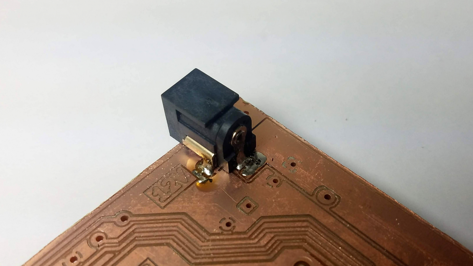
Install the female barrel jack in the upper-right-hand corner of the board.Install the Capacitors
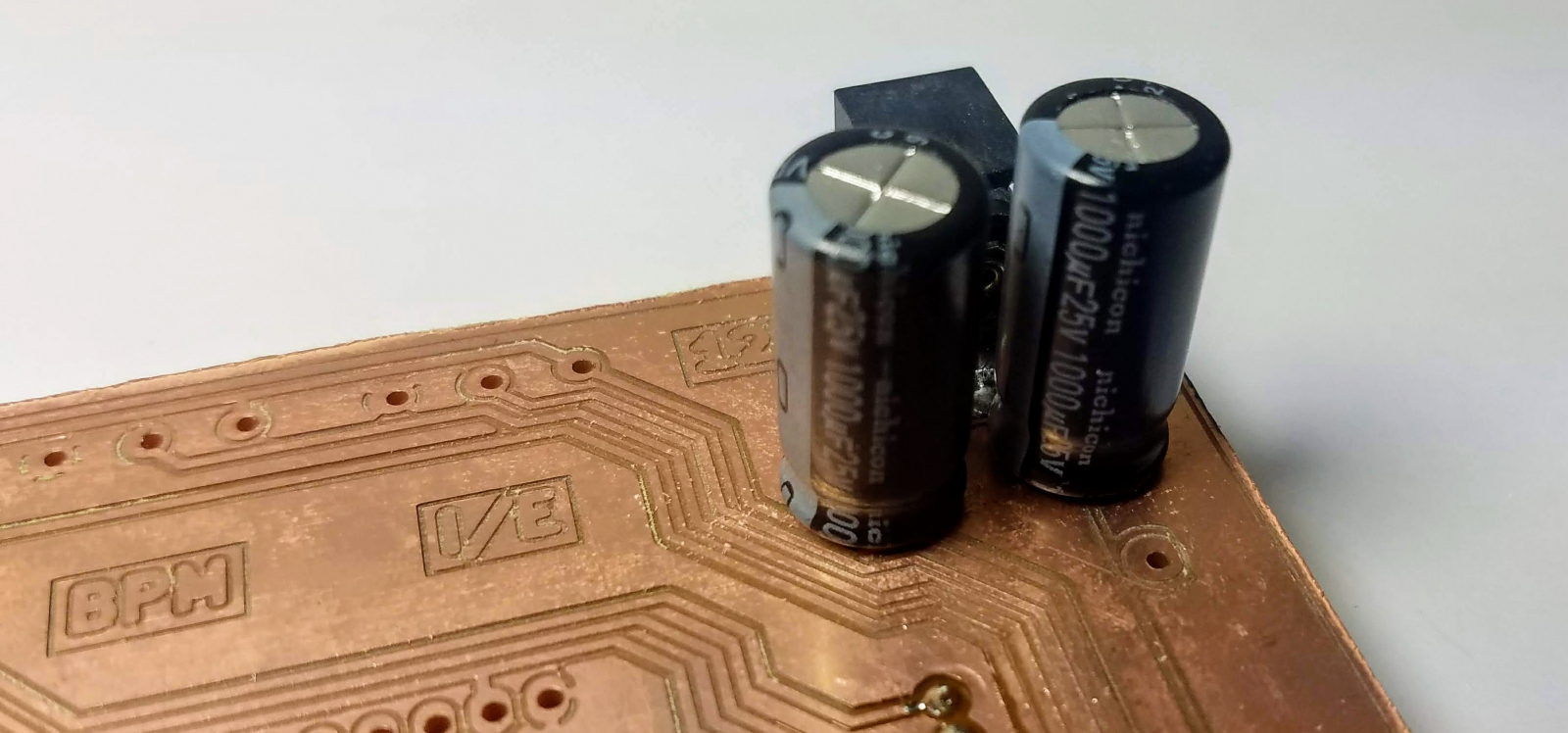
Install the two 1000uF capacitors near the barrel jack. The direction is important! Make sure the stripes on the capacitors face the middle of the board, or they will violently explode!Install the Potentiometers
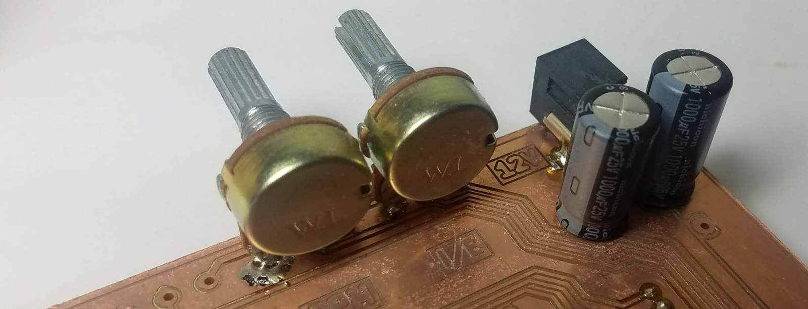
Install the two potentiometers to control the BPM and I/E of the ventilator.Soldering is Complete!
The soldering is now complete! Your finished board should look something like this:Add Hot Glue for Strength
To make sure the potentiometers are secure, add hot glue around their bottoms, both front and back. It is very important that you do this otherwise, they may break leaving you unable to set CPM or IE.Add Insulation
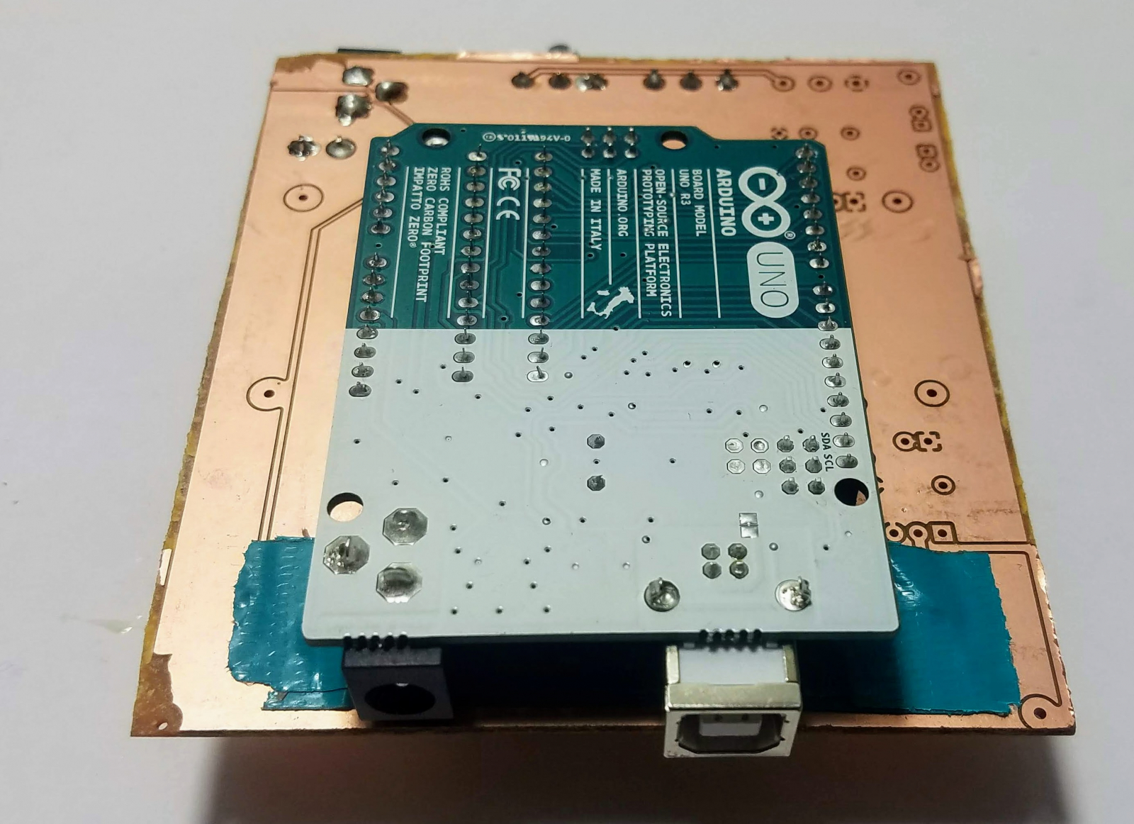
The USB connector on the Arduino is metal, and might accidentally short-circuit the valve connections. You can prevent this by cutting the terminal block wires very short, and adding two layers of duct tape under-neath the terminal blocks. You must do this.Upload the Arduino Program
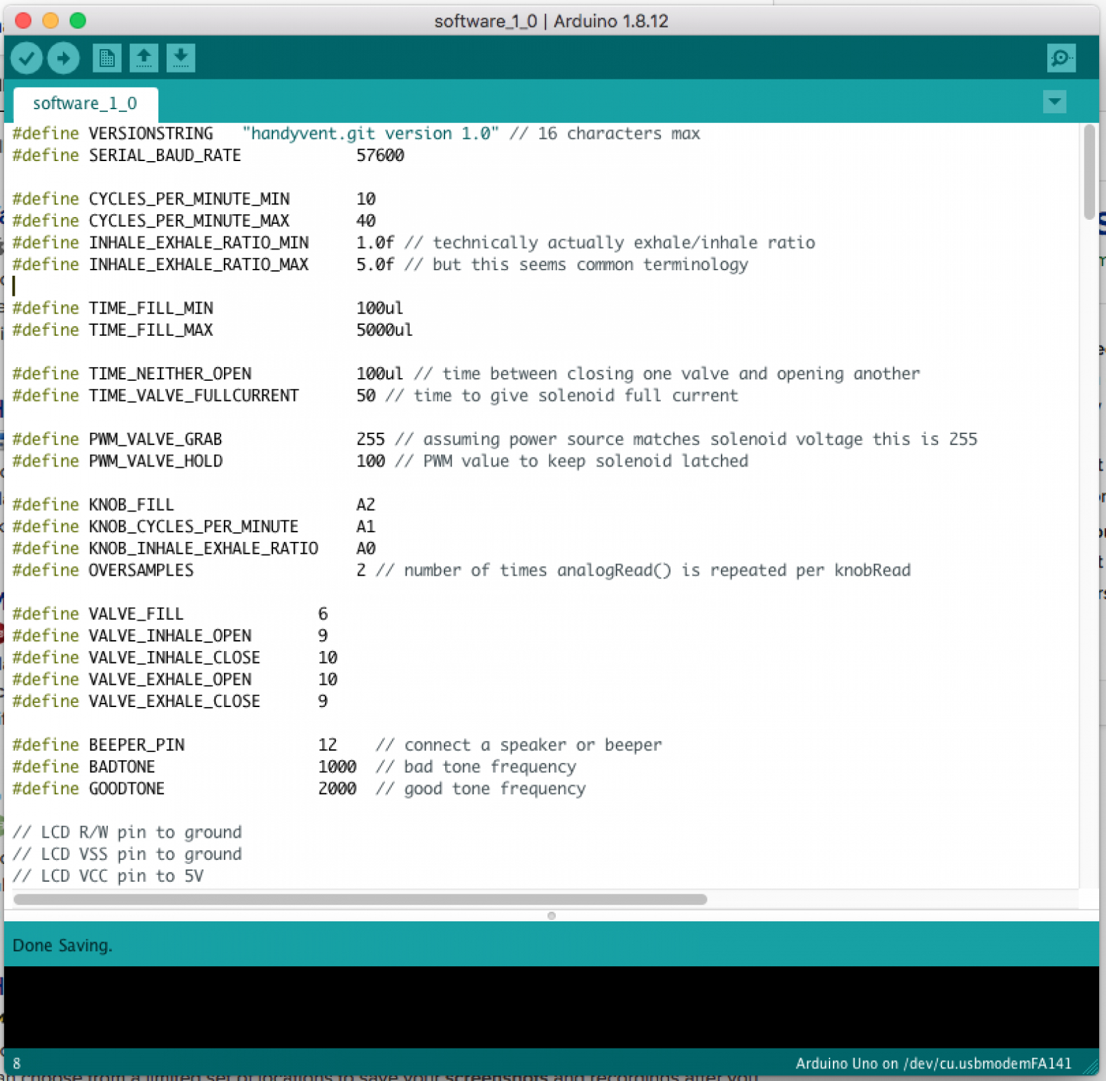
Download the Arduino program from the gitlab repository, and upload it to the Arduino over your USB cable. Even if you chose the correct serial port, the software might report that the upload failed. If this happens, unplug the Arduino from the circuit board and try again. This usually solves the problem.Wiring up the Circuit Board
You will need to wire the valves to the terminals on the circuit board like so:- Connect the +12v (black) wire of the inspiration valve to "E"
- Connect the +12v (black) wire of the expiration valve to "G"
- Connect the OPEN (green) wire of the inspiration valve to "D"
- Connect the CLOSE (white) wire of the inspiration valve to "H"
- Connect the OPEN (green) wire of the expiration valve to "J"
- Connect the CLOSE (white) wire of the expiration valve to "F"
- "A", "B", "C", and "I" are not connected.