IEC Fusion Reactor MK III
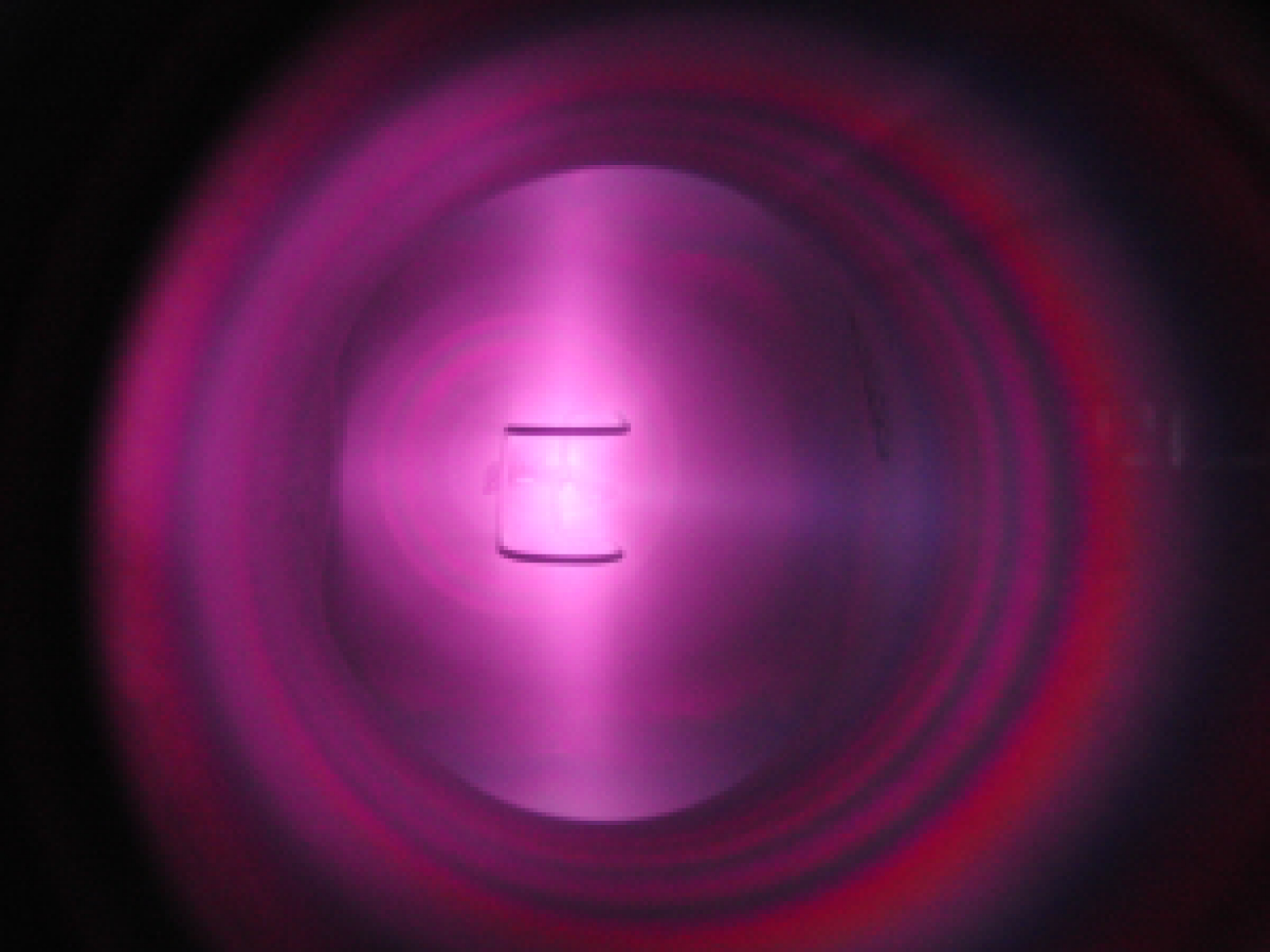
Recently I've been working on a new reactor, IEC Fusion Reactor MK III. Unlike its predecessor, MK III is based in a small, 1.5 in diameter, cross shaped chamber. Small reactor designs have shown promise of high efficiency and high neutron rates, and I would like to personally investigate these claims. Additionally, I intend to use this reactor to begin investigation into the neutron activation of elements, an area of research that will require long run times and high neutron fluxes. Finally, the reactor will serve as an experimental test bed for new ideas that come to my mind. I've constructed the reactor partially; the new chamber is currently mounted on reactor MK II's old frame. I've also tested the reactor to a small extent, with a max neutron rate of 21800 n/s TIER, however it's been held back from its full potential due to grid arcing, pressure control issues, and minor amounts of outgassing.Some updates (coming soon!) are a new throttle valve, and a new t-slotted aluminum frame. I will also be setting up a gamma spectrometry system soon, and will begin activation experiments.IEC Fusion Reactor Mk. III was designed as a smaller, more compact IEC reactor, capable of being easily expanded and experimented on. Here’s a picture of the finished reactor, and another of the reactor operating.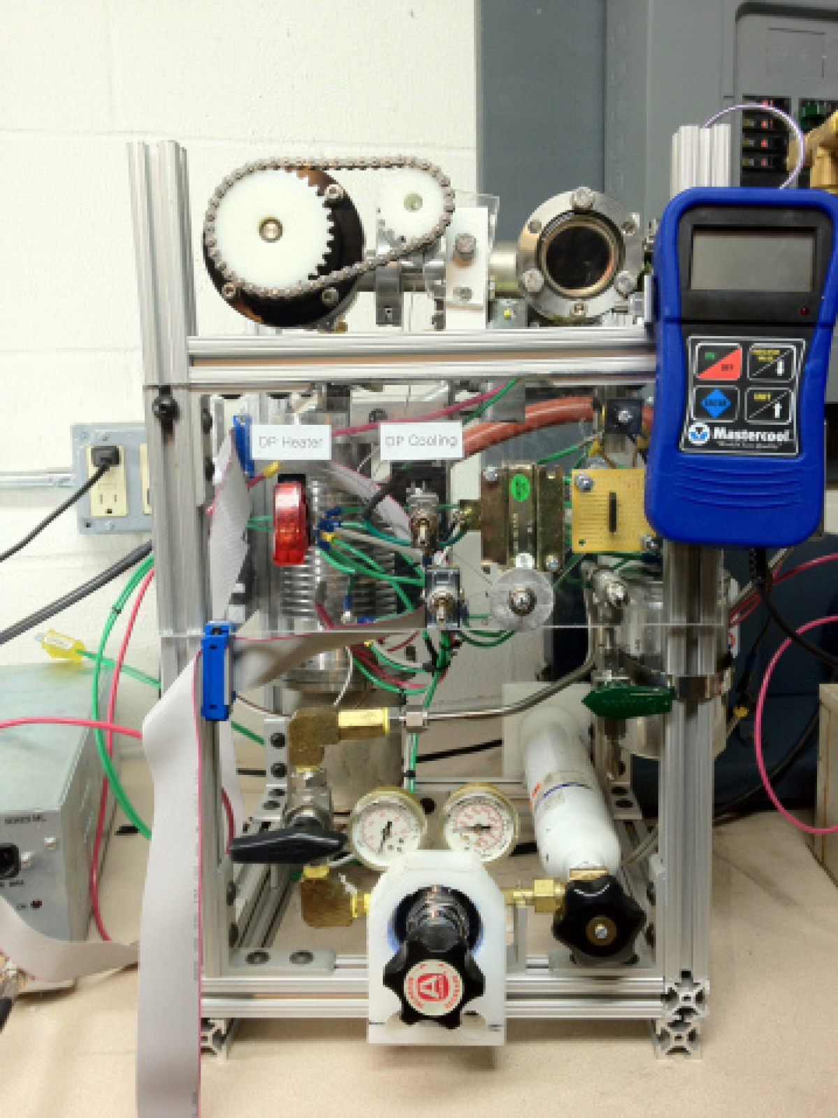
 The reactor consists of subsystems described below:
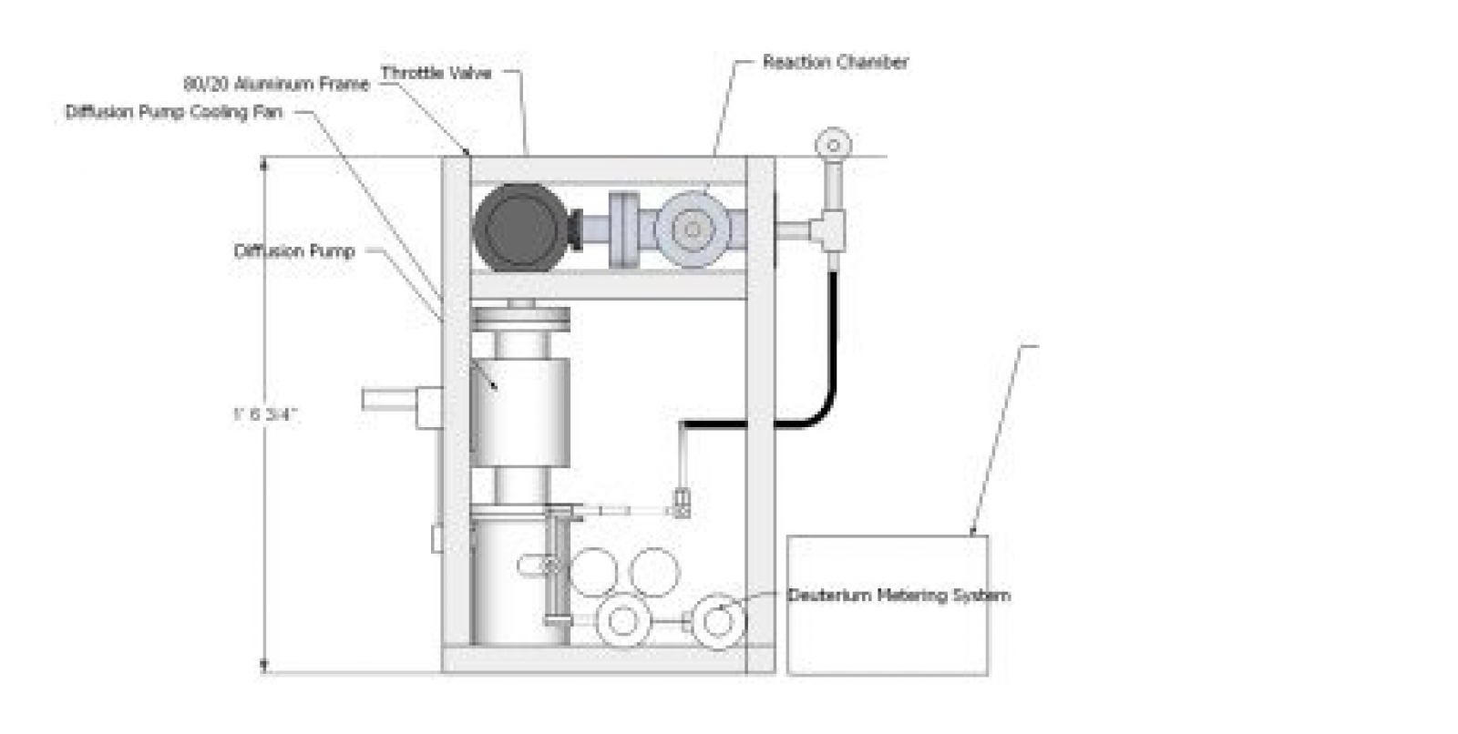
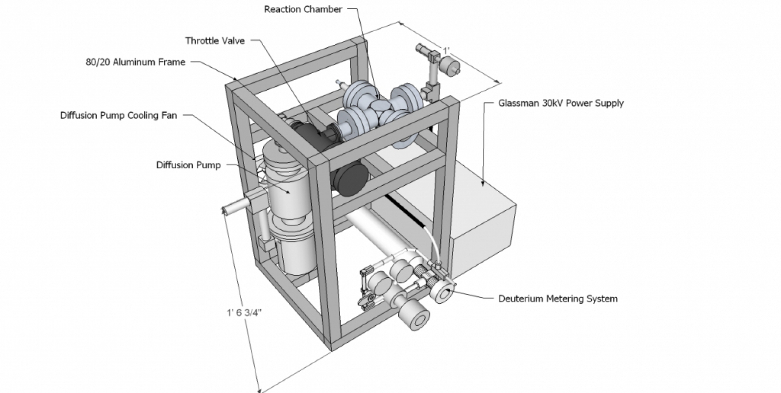
 You can also see the reactor’s throttling valve to the left of the reactor’s chamber. Connected to this is a Veeco EP-2A air cooled diffusion pump, capable of reducing the chamber’s pressure to <10^-4 millitorr. This pump is cooled by two 120v fans that circulate air across a heatsink built into the pump body. This pump cannot operate until the pressure is around 200mTorr, so in order to decrease the pressure to that point, a single stage rotary vane Welch 1399 mechanical pump is used.Diffusion pumps are convection based, high vacuum pumps that basically heat oil to the point where it vaporizes, rises at an extremely high speed, and then is directed downwards in a series of jets while simultaneously being cooled and condensing. These oil jets force gas molecules towards the bottom of the pump. The old system used a fan from an air mattress inflator to push air over the pump’s heatsink (in order to allow for condensation of the oil vapor to occur). This fan produced lots of vibration, as well as an extremely loud, high pitched noise. I’ve replaced it with two 115v, 25W computer fans, which will work in tandem to pull and push air over the pump’s condenser section heatsink. Another prospect I’m looking at is that of a remote control system for the reactor. I’m planning on creating a relatively simple system to control pumps, fans, valves, power supplies, etc. from 10-15 feet away from the reactor. This will merely serve to keep neutron radiation doses as low as reasonably possible as I approach higher levels of operation (hopefully 500,000 – 1,000,000 neutrons/sec total isotropic emmission rate). This goes in accordance with the old proverb: “Nothing beats getting the hell away from a source of radiation.” -Unknown
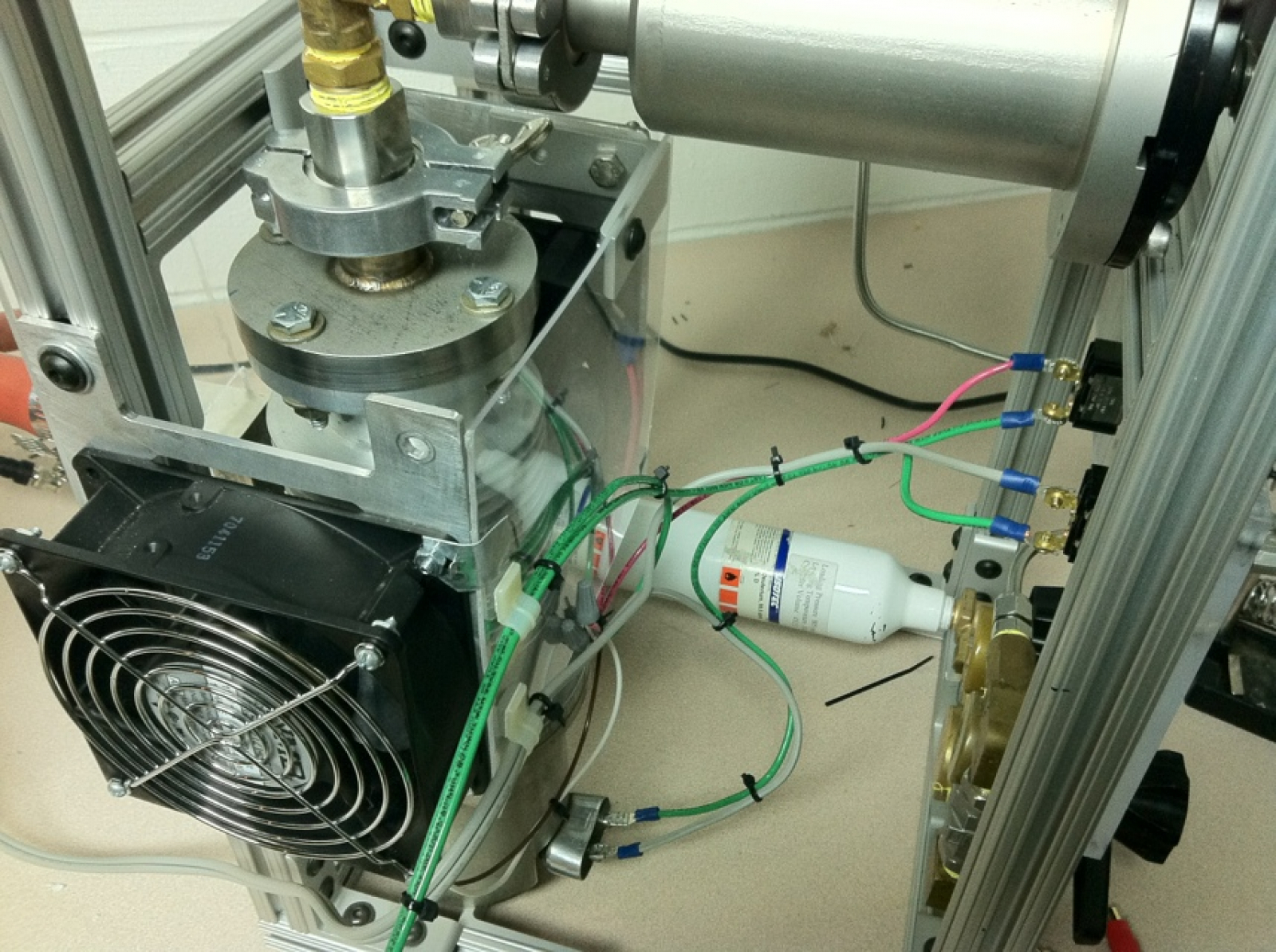 The rest of the reactor’s control system will be comprised of a remote control unit attached via a 25′ long 25 conductor cable to the reactor, and 25 conductor cable from the reactor to the 30kV power supply. The control unit will have the following capabilities: displaying reactor voltage, reactor current, power supply on/off, and a momentary DPDT (double pole, double throw) switch to adjust the position of the reactor’s main throttle valve.The display of current and voltage will be achieved through the use of two analog panel meters, reading the voltage across pins on the power supply. The power supply on/off will be accomplished by a SPST (single pole, single throw) switch across the “common” and “HV enable” pins of the power supply.The control of the main valve will be slightly trickier. A 120v to 8v transformer, and bridge rectifier will supply a 3 RPM motor with DC power. This motor will connect via a chain drive connecting it to the valve. This assembly will allow the valve to open and close at a rate of around 8 degrees/second. The DPDT switch in the control unit will be wired so that the DC motor can be driven in a forwards or reverse direction.Additional information that will be available remotely will be the totalized neutron count, pressure in the chamber, and a remote view through the reactor’s viewport, although these still have to have the details worked out.
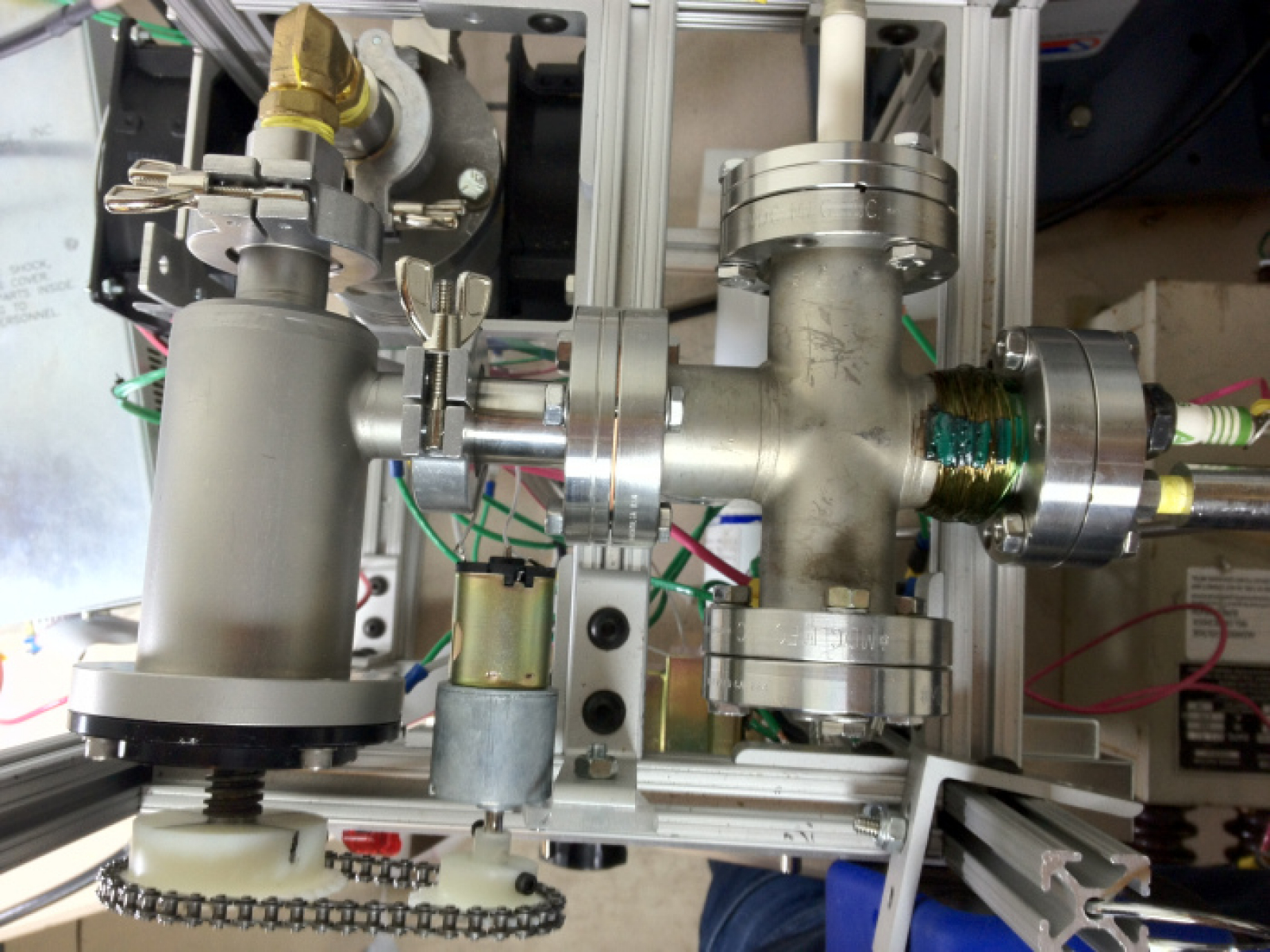
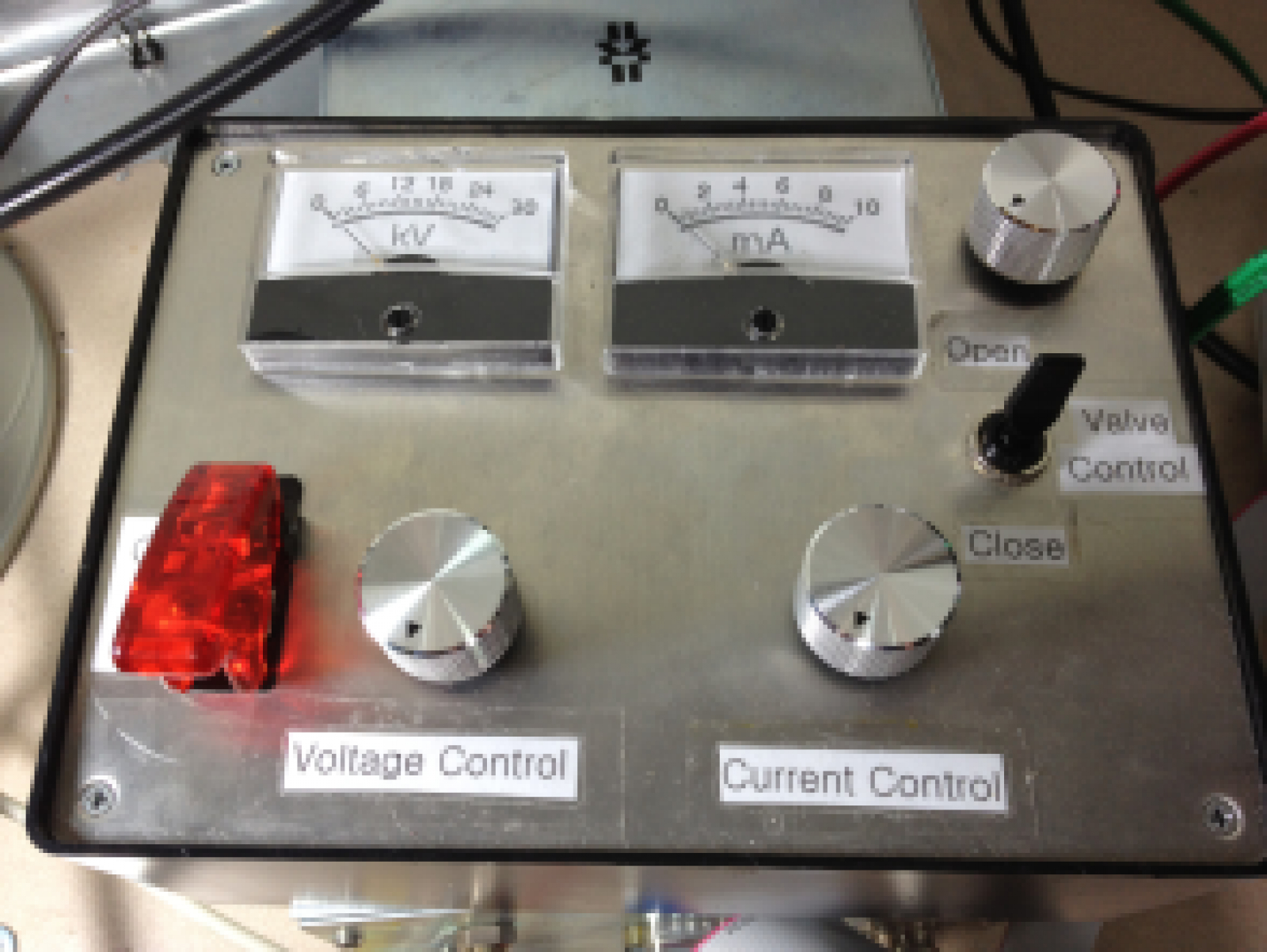 In order for the valve to be remotely controlled, an 8 RPM gearmotor was connected via chain to the shaft of the valve. A 14 tooth sprocket was attached to the motor driveshaft, and a 30 tooth gear attached to the control shaft of the valve. This gearing reduces the maximum rotational rate of the valve to 3.73 RPM, or 22.4 degrees/second. This correlates to a change in the position of the valve’s sealing face of 1.3 percent of maximum travel distance/second. This system is controlled via a simple circuit consisting of a DPDT switch and potentiometer (for speed control) housed within the reactor controller. The motor is powered by a rectified transformer in the reactor’s body.
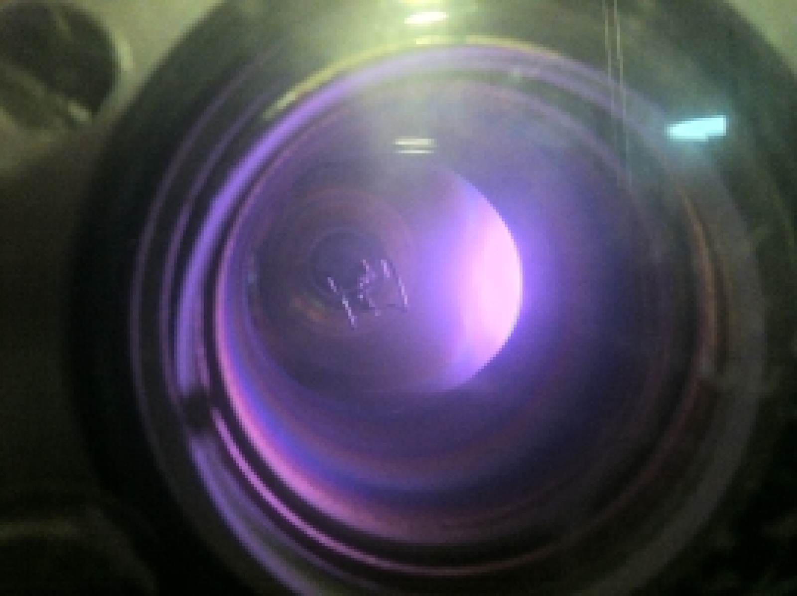 Neutron Detection System:The neutron detection system consists of a boron-10 lined proportional tube placed in a water based neutron moderator, read by a Ludlum Model-3 at 772v bias. The function of the neutron moderator is to decrease the energy of the high energy “fast” neutrons from the reactor to low energy thermal neutrons that the B-10 tube can detect. This also allows one to test if the neutron detection system is detecting anything other than neutrons from the reactor. If the system counted things such as EMI or x-rays, the count rate inside and outside the moderator would be identical. However, the tube cannot detect neutrons with the moderator off the tube, and therefore, an un-moderated tube, calibrated properly,should not produce a high count rate when placed next to the IEC reactor. A moderated tube, calibrated properly would produce a high count rate. This test was carried out, and shows evidence that the reactor generates neutrons rather than EMI or x-rays alone.
Frame
The reactor is built around a frame of 80/20 aluminum extrusions. 80/20 aluminum is some great stuff, it’s expandable, easy to cut, easy to mount stuff on, and very structurally sound. The frame was designed with ease of use, adaptability, and good geometry for experimentation in mind. The frame will house all the reactor's components minus the neutron detection system, roughing pump, and high voltage power supply.Cathode
The reactor’s main accelerator cathode is made of tungsten wire, however I have experimented with other grid materials as well.Vacuum System
The reactor is housed in a small 2.75″ 4-way conflat cross chamber, a big difference from reactor MK.II’s 6″ diameter spherical chamber. On this chamber, there is a 2.75″ CF to NW 25 adaptor, a 30kV feedthough, an ion source mounted on a blank flange, and a 2.75″ viewport. A top view of the chamber is below.Gas System
The gas system consists of a 25L bottle of deuterium gas leading to a single stage regulator, through a shutoff valve, to a low-flow metering valve, though another shutoff valve, and into the chamber. The connections are 1/4″ stainless swagelok and NPT predominantly, with the exception of a CGA 180 fitting in between the tank and valve. Essentially, what this setup allows me to do is greatly reduce the deuterium pressure from the bottle, leading to a low flow rate into the reactor chamber.High Voltage Power Supply
A Glassman ML30 30kV, 10mA power supply was used for the reactor power supply. It interfaces with the reactor and controller via a DB25 cable.Remote Control System
I’ve mentioned in earlier posts that my next reactor will be remotely controlled, however I haven’t really gone in depth as to why. Well, it really all comes down to minimizing neutron dose. While the x-rays the reactor emits from the viewport are extremely easily shielded, the neutrons, which are emitted in all directions, are exceedingly hard to stop. Although the reactor currently operates at a measly 30,000 neutrons a second (total isotropic emission), I plan for this next reactor to be able to reach outputs of >= 1,000,000 neutrons/second TIER, and hopefully sustain those outputs for an extended period of time (~30 minutes).This will allow for a myriad of experiments to be performed. Now, at these levels, the radiation hazard becomes somewhat troublesome. With shielding the neutrons not being a truly viable option, I have no choice but to get away.By my calculations, operating at 1,000,000 2.45MeV neutrons/sec while standing 2.5′ away would result in a dose rate of 1.71 mrem an hour. While this is not terribly high, it is still wise to keep dose rates as low as reasonably possible. However, at 25 feet away, the neutron dose rate plummets to a minuscule .017 mrem an hour. As a comparison, the average airline flight clocks in at .5 mrem an hour at cruising altitude.So far I’ve only installed two switches, one to operate the diffusion pump heater, and the other to operate the diffusion pump cooling system. These switches just switch 120v 60hZ AC from to wall, and are mounted on the reactor itself, as they will not need to be operated while the reactor is producing radiation.The full remote control system is housed in a project housing from Radioshack and interfaces with the reactor and Glassman ML30 high voltage power supply via a DB25 cable. A simple covered switch on the controller allows for the power supply’s interlock to be remotely operated. The controller uses 1 mA panel meters to measure voltage and current. The meters are in series with a 10k resistor which is built into the supply, and are each connected to a 0-10v signal that varies directly proportionally to the voltage or current being output by the supply. Due to the 10k resistor, the 1mA panel meters are driven to full scale when the signal reaches 10v. The controller also offers remote control of the main throttle valve of the reactor.Ion Source
A DC magnetron ion source was built for reactor MK. III. I’m in the development of some other sources at the minute as well.