Portable X-Ray Machine
The goal of this project was to build an inexpensive portable x-ray machine, since such a device didn’t seem to exist! Odd, since such a machine could prove to be very useful in remote or underequipped areas such as army camps or poorer countries.The full paper detailing this endeavor may be downloaded here, but the text below provides a general synopsis of the project.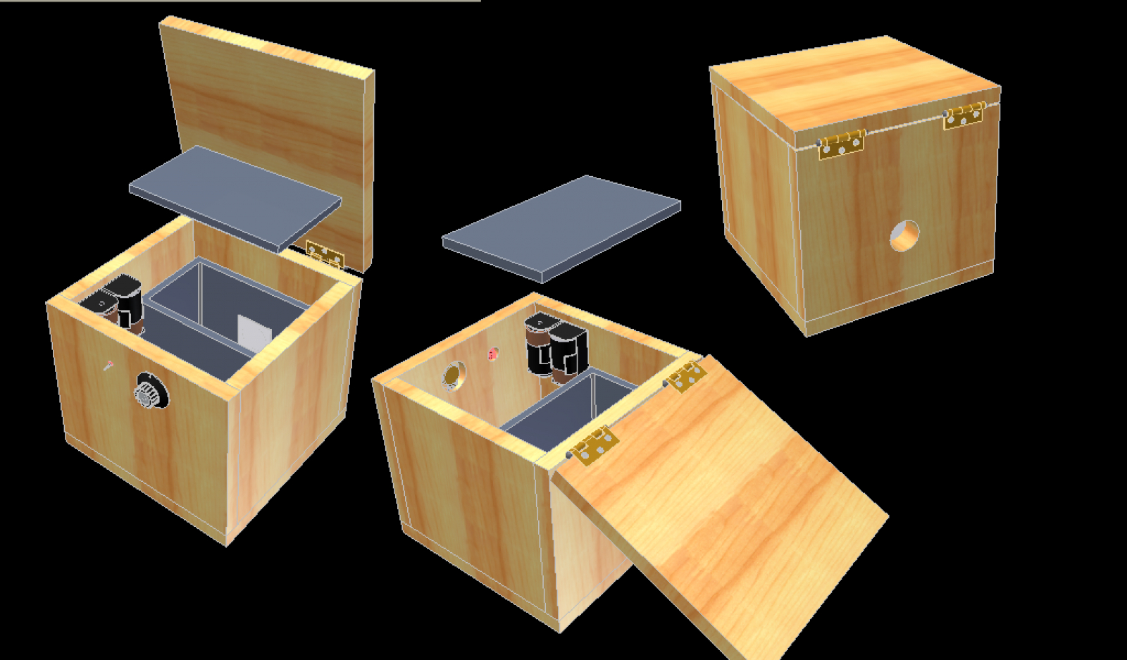 I began a long tedious process of making yet another lead box, this time by first cutting out the shapes from clay, then casting the shapes in plaster. A form of lost-clay casting which would leave me with the 6 sides I could weld together.
  Sounded simple, but turned out to be a huge trouble due to water in the plaster that could not be baked out. After 5 attempts at casting the parts, I finally ended up with indecent, but usable shapes. They were then welded together to make an awesome hot box.
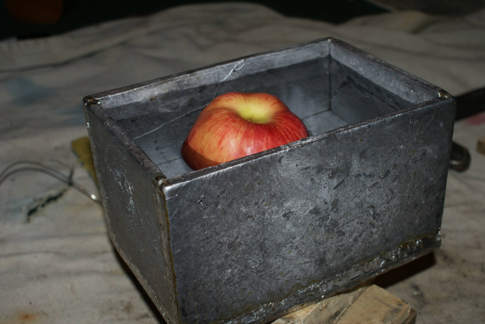 BUT THEN… my tube arrived in the mail and it was a bit smaller than I was expecting. So that box wasn’t going to work (I now use it to store my radioactive items). Yet another design was needed, and after a few months of on and off work the whole project turned out like this:
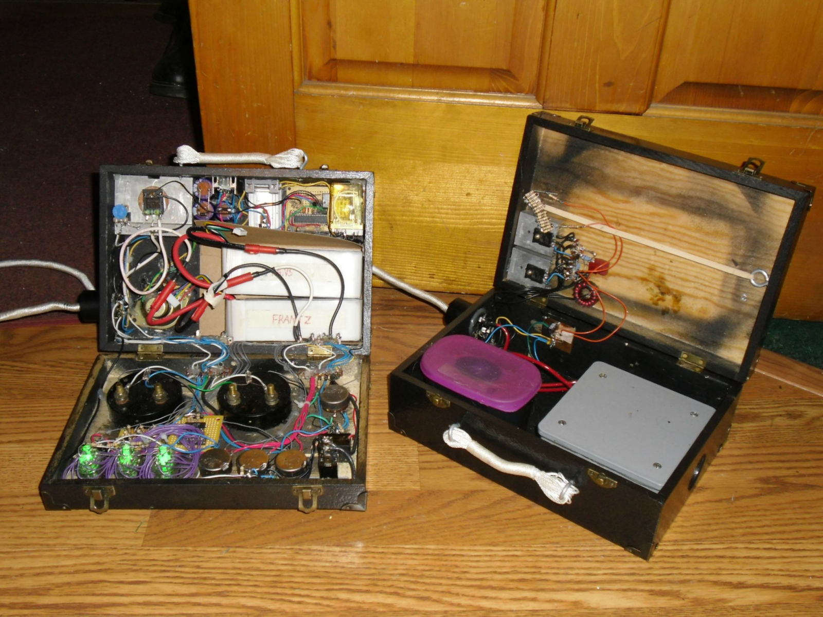
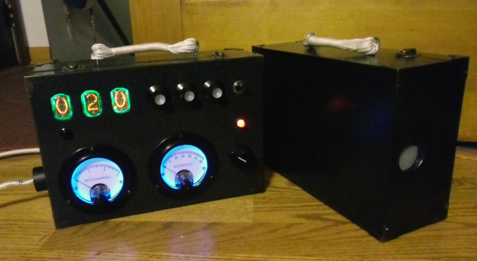 The machine is split into two parts: a control box and a ‘tube head’. The tube head is the part that houses the high voltage components and x-ray tube, while the control box houses most of the circuity and the power source (LiPo batteries). Both were designed to be beautiful: burned brass corners, hammered paint finish, unnecessary lighting of the switches, display and meters… Making the device look good took a whole month itself! They are connected via removable cable which utilizes two octal vacuum tube bases as the connectors.The control box features a multiplexed nixie display, three dials to set the exposure time, another dial to set the kVp as well as two meters to monitor the coolidge tube current and voltage. Along with those controls we have a button to display the oscillator voltage, as well as a speaker and the on-off switch. And of course, the expose button.
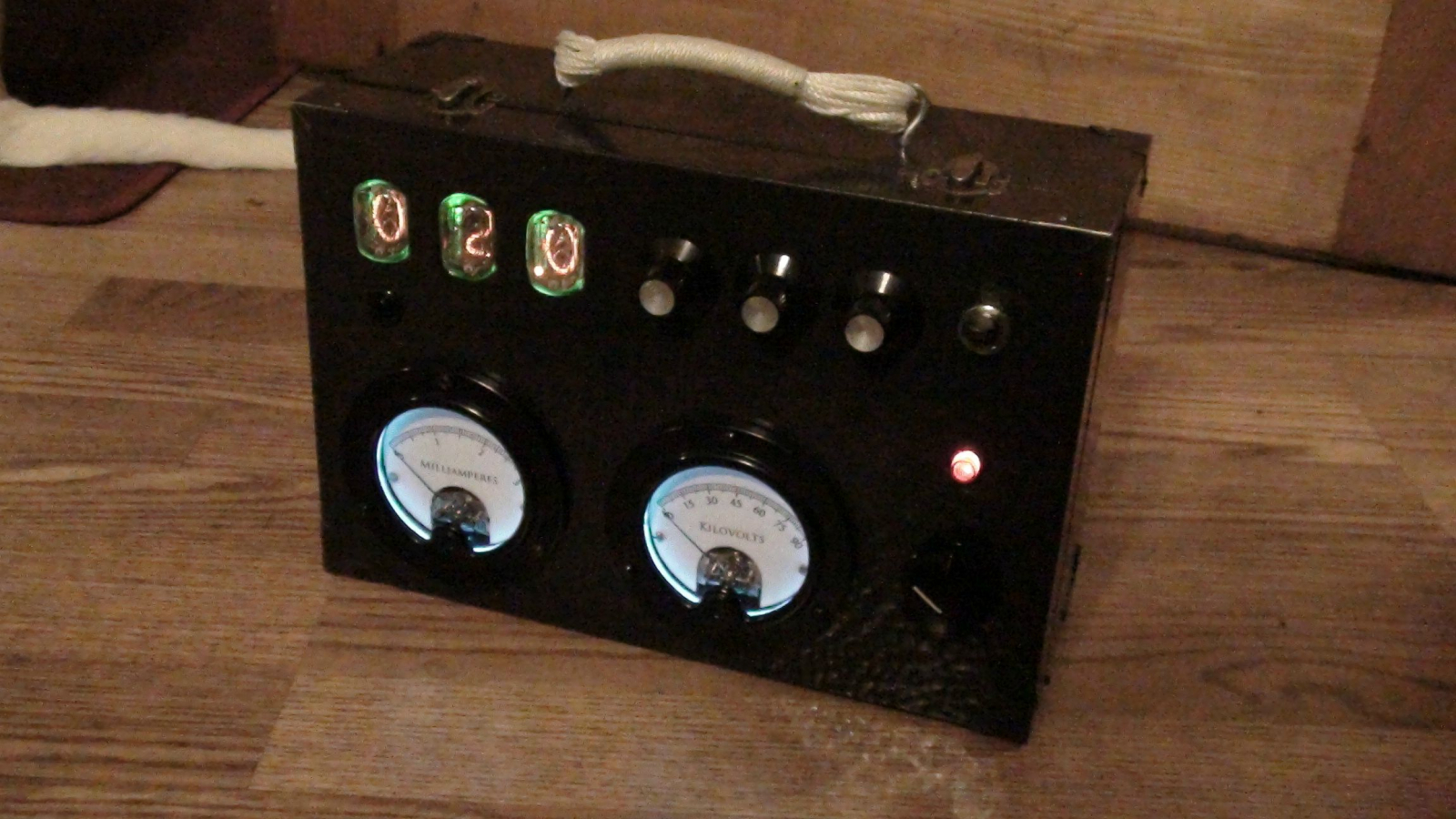 The two meters were a mini-project in themselves. When I bought them from a person on ARF, one measured 0-3mA while the other metered 0 to 10V. After removing the voltage divider resistors on the 10V meter, it turned out that full scale was 50uA. Wow that is sensitive, in order to create a 0 to 90kV meter I needed 1.8 billion ohms of resistance in series with the meter! Making the meters glow was achieved with clever placement of EL wire, but I seem to have lost the photos of that process.
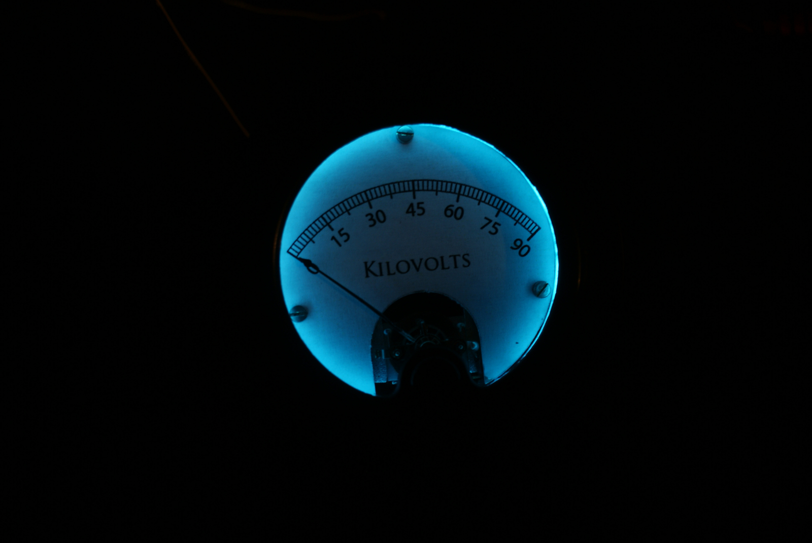 Compared to the outside, the inside of the control box looks to be a disgraceful, awesome rats nest of wires. The brains of the device is an Atmega 368 programmed with the arduino bootloader. I chose a micro-controller over state logic so it’d be easier to add features later. In the end there isn’t much room for improvement however considering I used all but 1 pin! 7 pins are used to drive the multiplexed nixie display, 3 more are used as analog inputs, while another two are used to switch a pair of relays. The rest preform various functions such as monitoring voltages.
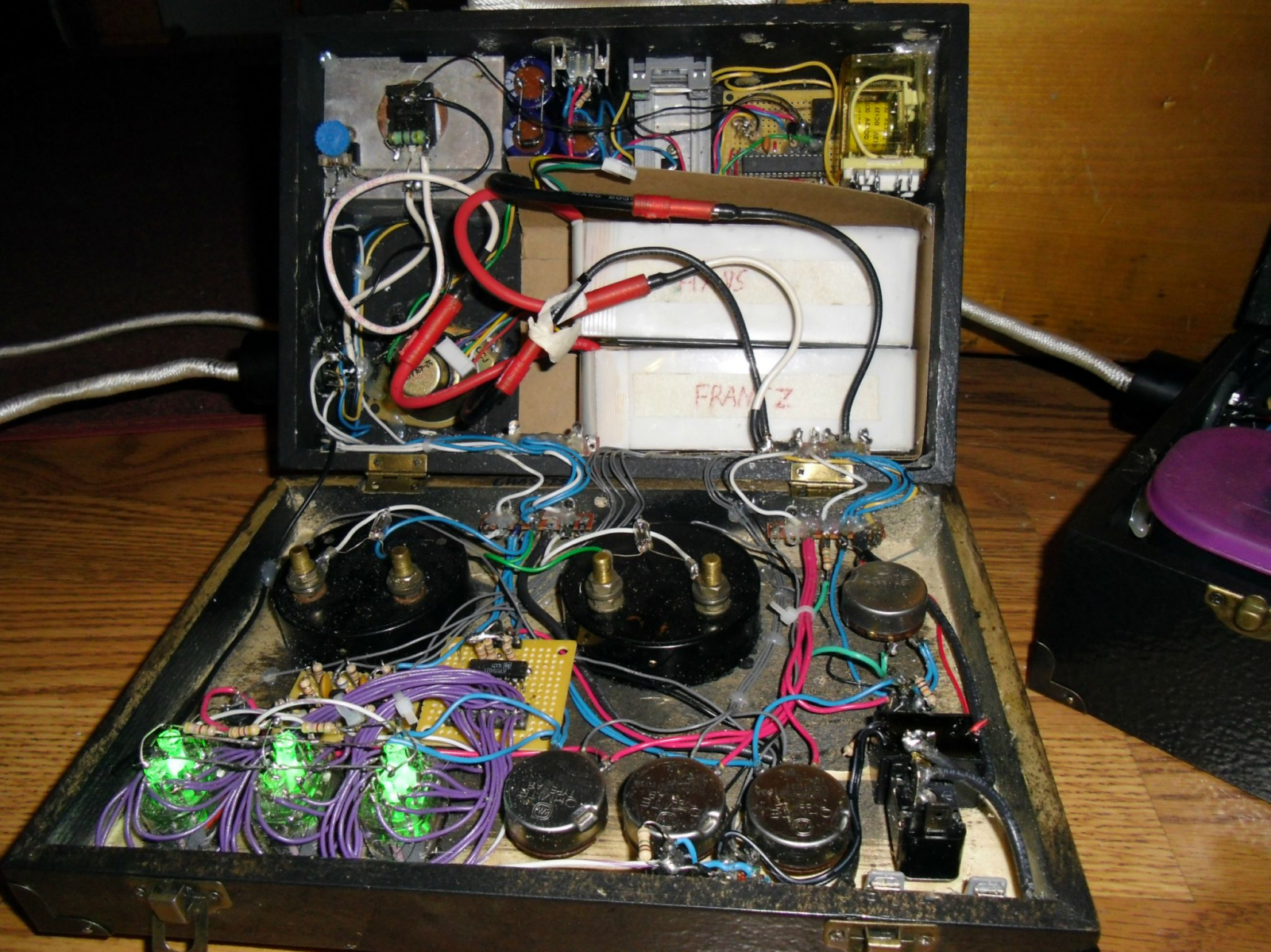
 At the end of the countdown a second relay switches on and turns powers up the HV circuit. The regulator voltage is now given to a ZVS oscillator which churns out 65kHz AC. This power is then sent into a homemade transformer where it’s stepped up to 20kVAC and fed into a cockroft walton multiplier. After multiplication we are left with anywhere from 40 to 75kV (adjustable) which then gets applied to the tube’s anode and makes x-rays. Oh and yes, the CMOS microcontroller shares the same chassis ground as the 75,000V rail. During x-ray production the nixie tubes glow red and a buzz from the speaker is emitted.
As you can see by the GM tube’s screams, not only does the machine in fact work, it’s pretty scary too. At 1 foot there are >8,300 counts per second: so intense that the geiger tube doesn’t even have enough time to recover between events!
At the end of the countdown a second relay switches on and turns powers up the HV circuit. The regulator voltage is now given to a ZVS oscillator which churns out 65kHz AC. This power is then sent into a homemade transformer where it’s stepped up to 20kVAC and fed into a cockroft walton multiplier. After multiplication we are left with anywhere from 40 to 75kV (adjustable) which then gets applied to the tube’s anode and makes x-rays. Oh and yes, the CMOS microcontroller shares the same chassis ground as the 75,000V rail. During x-ray production the nixie tubes glow red and a buzz from the speaker is emitted.
As you can see by the GM tube’s screams, not only does the machine in fact work, it’s pretty scary too. At 1 foot there are >8,300 counts per second: so intense that the geiger tube doesn’t even have enough time to recover between events!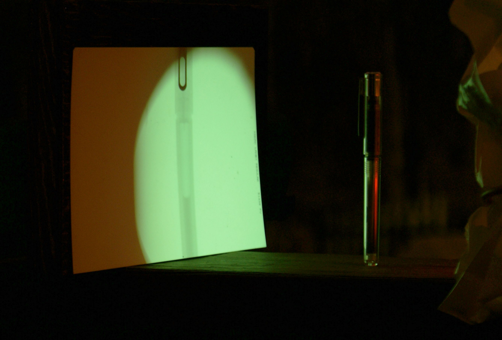
The Machine
The design has gone through several revisions on its two year journey. The first alliteration was designed to be a self-contained unit that emitted no stray radiation. I even went as far as building a huge lead box for it! The box was constructed by melting wheel weights into a hobo-pie maker to make square plates, then welding them together with a blowtorch. It took 2 weeks, 6 hours a day to make! But at the end I realized how unreasonable it would be as the box was so heavy that it was immovable…So the lead was melted down and a new design drawn up in autodesk. This version was to be a plywood box with an inner lead box, and it was to emit a beam of x-rays. Simple enough.Method of Operation
The microcontroller constantly polls the three time setting knobs when the machine is idle. By mapping each knob to a 0-9 scale, 3 numbers can be established and combined to form 3 digits: 10’s, 1’s and tenths. These are then printed to the nixie display, one tube at a time over a span of 2 milliseconds. As it takes 2ms to write a number to the display, the printNixie() routine was used as the time-keeping routine of the program. 500 printNixie() calls equates to 1 second of passed time, so by using that routine instead of delay() within the program allows the system to keep time without blanking the nixie display. I suppose this could be considered a hacked version of multitasking… maybe.After setting the exposure time, the desired anode voltage is set with the big knob. Turning this knob adjusts what voltage the regulator will be fed to the HV oscillator (14 to 35VDC). Pressing the black button will display this voltage on the nixie tubes, so it’s not just a shot in the dark every time you turn that knob. In the future I would like to add a feedback loop, having the microcontroller monitor the actual anode voltage and adjusting the oscillator accordingly.Once things are set, the expose button is pressed and a 10 second countdown ensues. At the beginning of this countdown a small relay switches on and supplies 14V to the tube head. That 14V is then stepped down to 3.5V via a buck converter and fed to the tube’s heater.X-Rays!
The performance of the machine was satisfactory, it was very capable of shining quite a lot of x-rays! I took some dosimetery measurements, but they were not very accurate as my equipment was overwhelmed by the x-ray flux.The machine produces copious amounts of radiation, certainly enough for radiography. As an experiment, a geiger-muller tube was placed at different distances from the machine and the results recorded in this video.Radiography
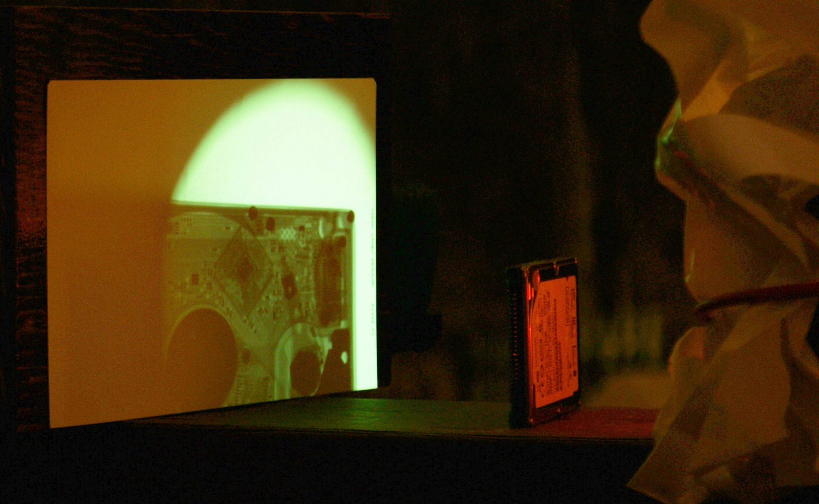
Of course there is no point in spending years building an x-ray machine if no pictures are taken with it! Below we have two of my first radiographs: a pen and a laptop hard drive. Since lenses do not work in x-ray land, making a radiograph is a shadow process: all images must be ‘shadows’ of the subject being imaged.X-rays are invisible and are only viewable via the use of a scintillation screen: a plastic/chemical sheet which fluoresces in the presence of ionizing radiation. Scintillation screens, or intensifying screens come in a multitude of sensitivities and colors, but the standard “fast” green one is the one most commonly available and used.