Air Valve V2
This air valve is made to be used with #HandyVent, or other similar ventilators.
Whenthese ventilators are used to treat COVID-19, any parts that were in contact with the patient should be throughly sanitized when they are switched from one patient to another. The advantage of this valve is that the air hoses are sealed, and do not directly expose the valve mechanism to air from the patient. I'm not a medical professional, but it seems like this would allow the valve to be more easily reused when transferring from one patient to another. This design is different from the #Laser-Cut_Double_Air_Valve because it bends the tube to create a crimp and restrict airflow, where the other version smashes the tube with a lever arm. Bending the tube seems to be a better method because it requires less force.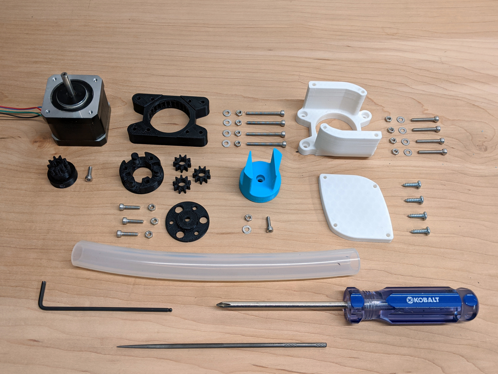 Parts List:
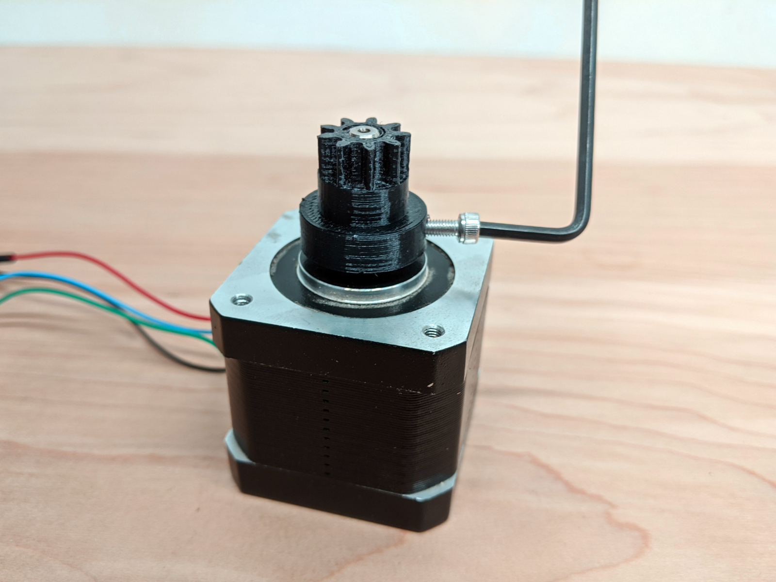 Fix the first gear to the Stepper Motor. A nut slots into the gear, and an M3 bolt functions as a set screw. The motor shaft should have a flat surface for the set screw to lock in place. If the shaft is fully circular, then a file or grinder can be used to make a flat spot.
 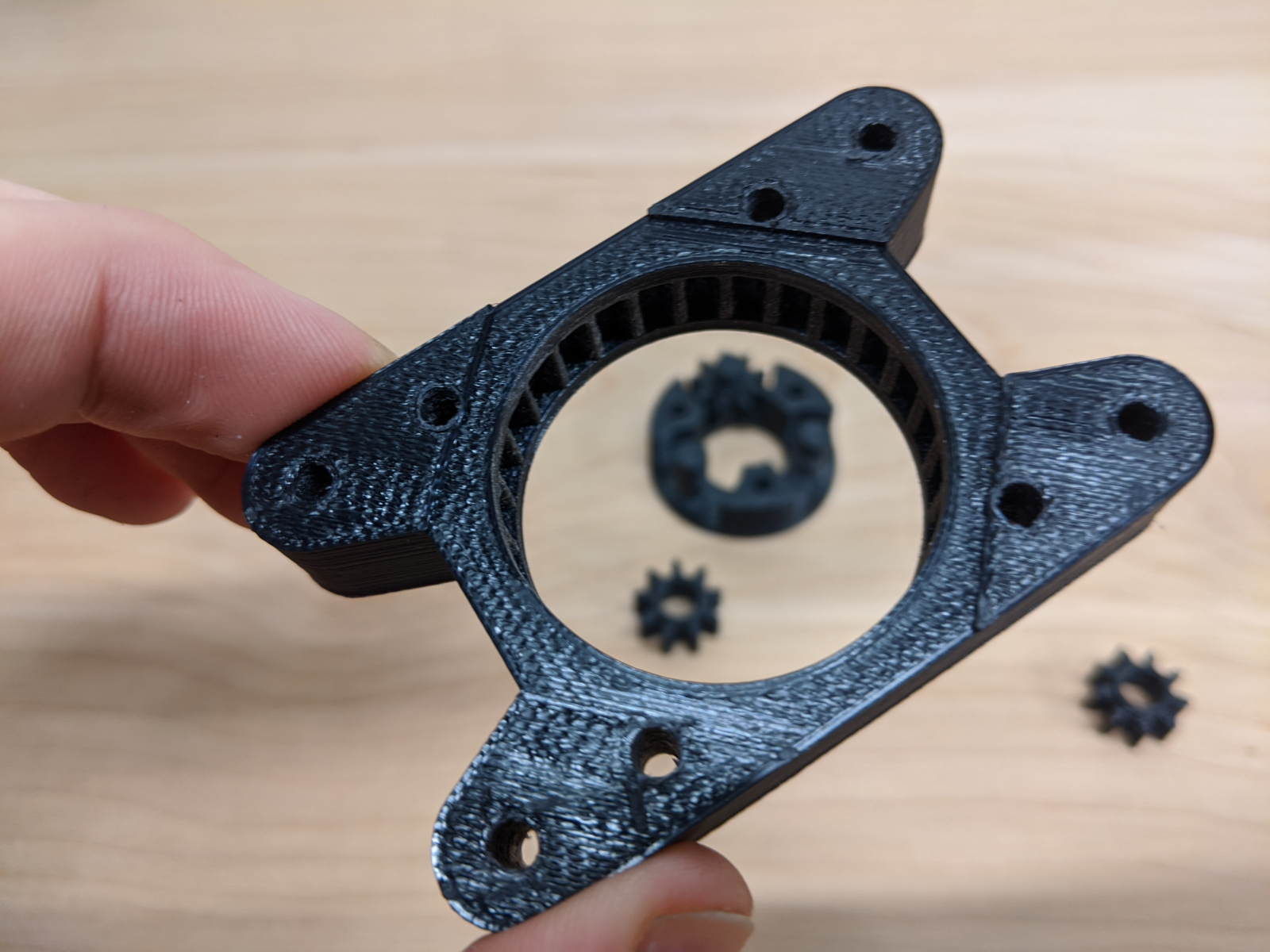 This part is a bit of a puzzle. The three gears must be put in place as the circular piece is inserted into the outer bracket.
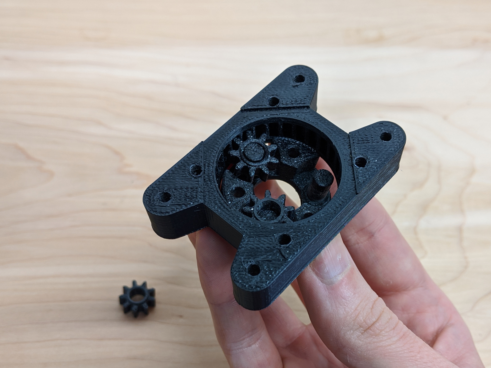
 After all three gears are in place, the circle crimper platform can be bolted in place.
  Three M3 bolts pass through the holes, hexagonal recesses are on the back side to capture the bolts.
  The blue crimper piece has four recessed holes in the bottom, one large one in the center, and three that line up with the heads of the bolts on the gear box. These recesses have overhangs, and they may need to be cleaned up in order for the crimper to fit properly.
  Put a single bolt through the center, add a nut to the bottom, and tighten.
 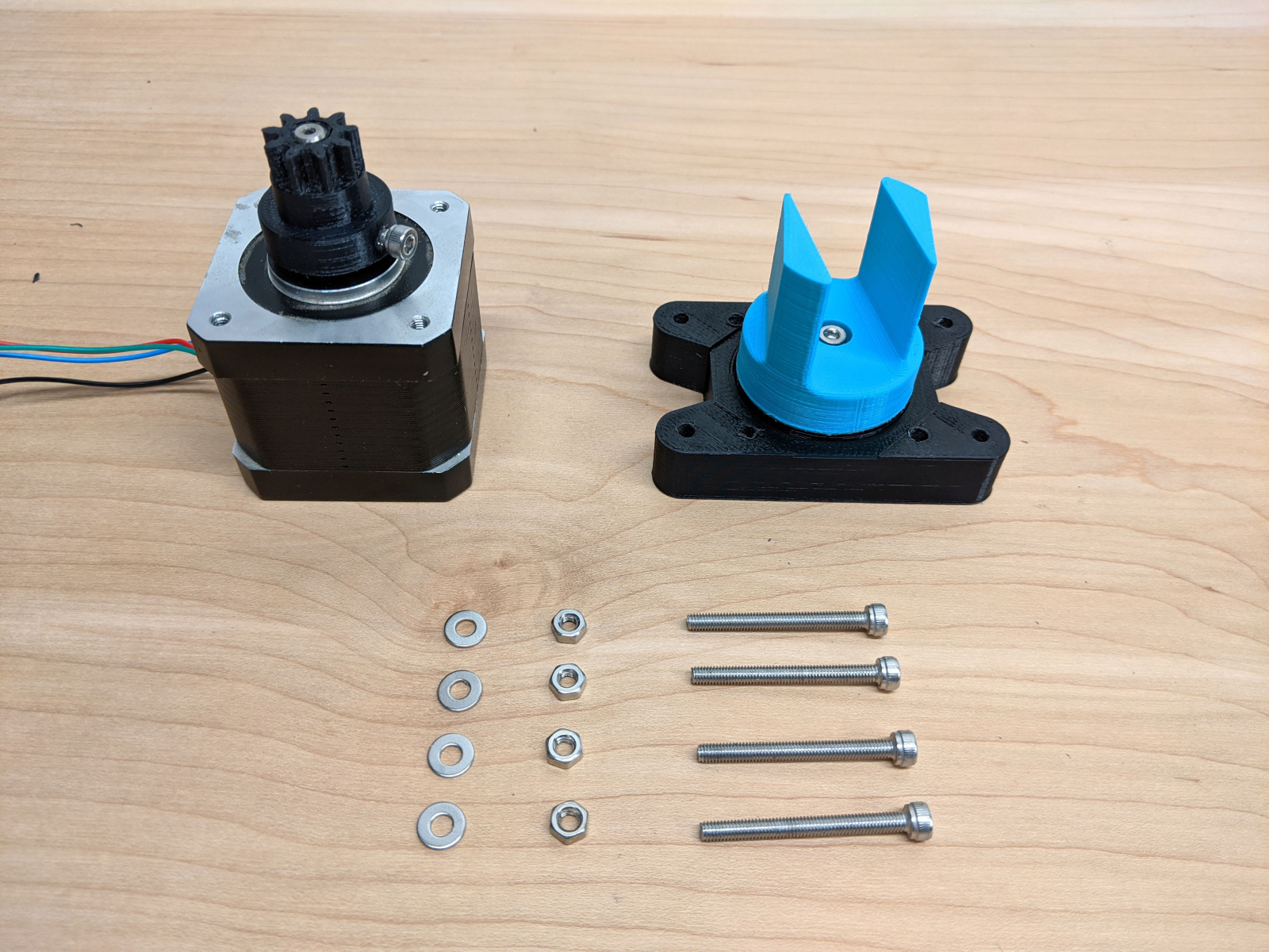 Four long bolts are used to attach the whole assembly to the stepper motor.
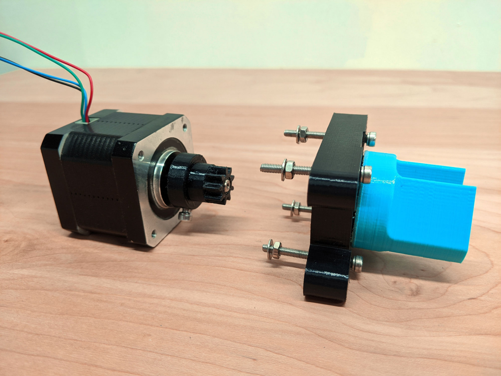 Pass all four bolts through the assembly. Spin the bolts about half-way up the nuts, then add washers.
 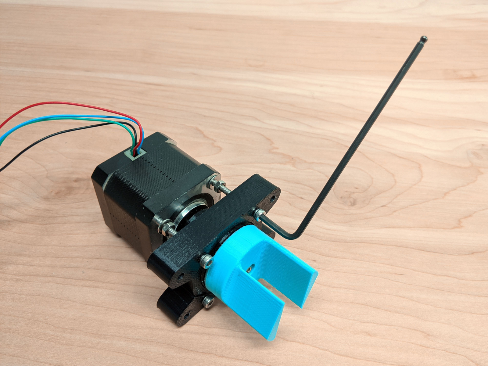 Fit the bolts into the stepper motor. Tighten them a bit, but not too much. If the assembly is too tight, it will make an absolutely terrible noise when the motor is running. Probably a good idea to plug things in at this point to make sure it spins okay. Once the assemble is appropriately fitted, tighten the bolts to lock everything in place.
 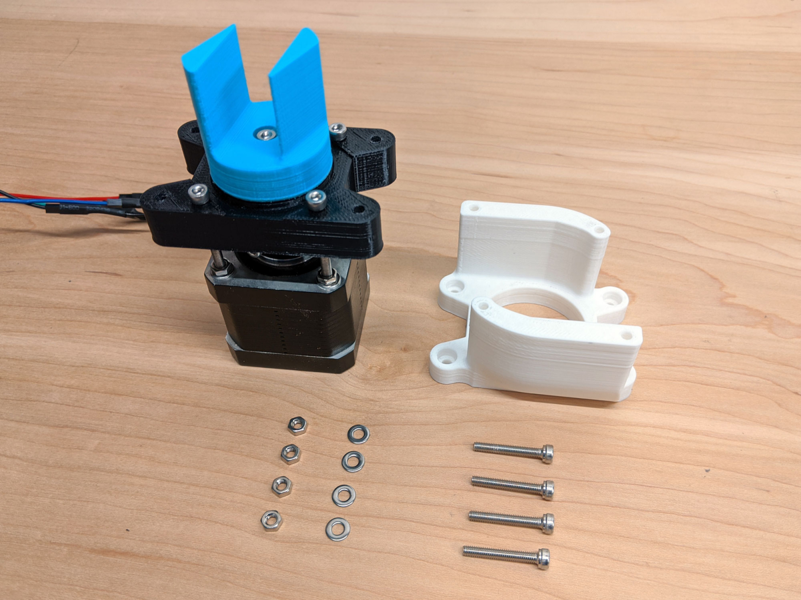 The outer housing should fit in place. There are four recessed holes in the bottom that line up with the bolts that were installed in the previous step. Again, these holes may need to be cleaned up for this part to fit.
 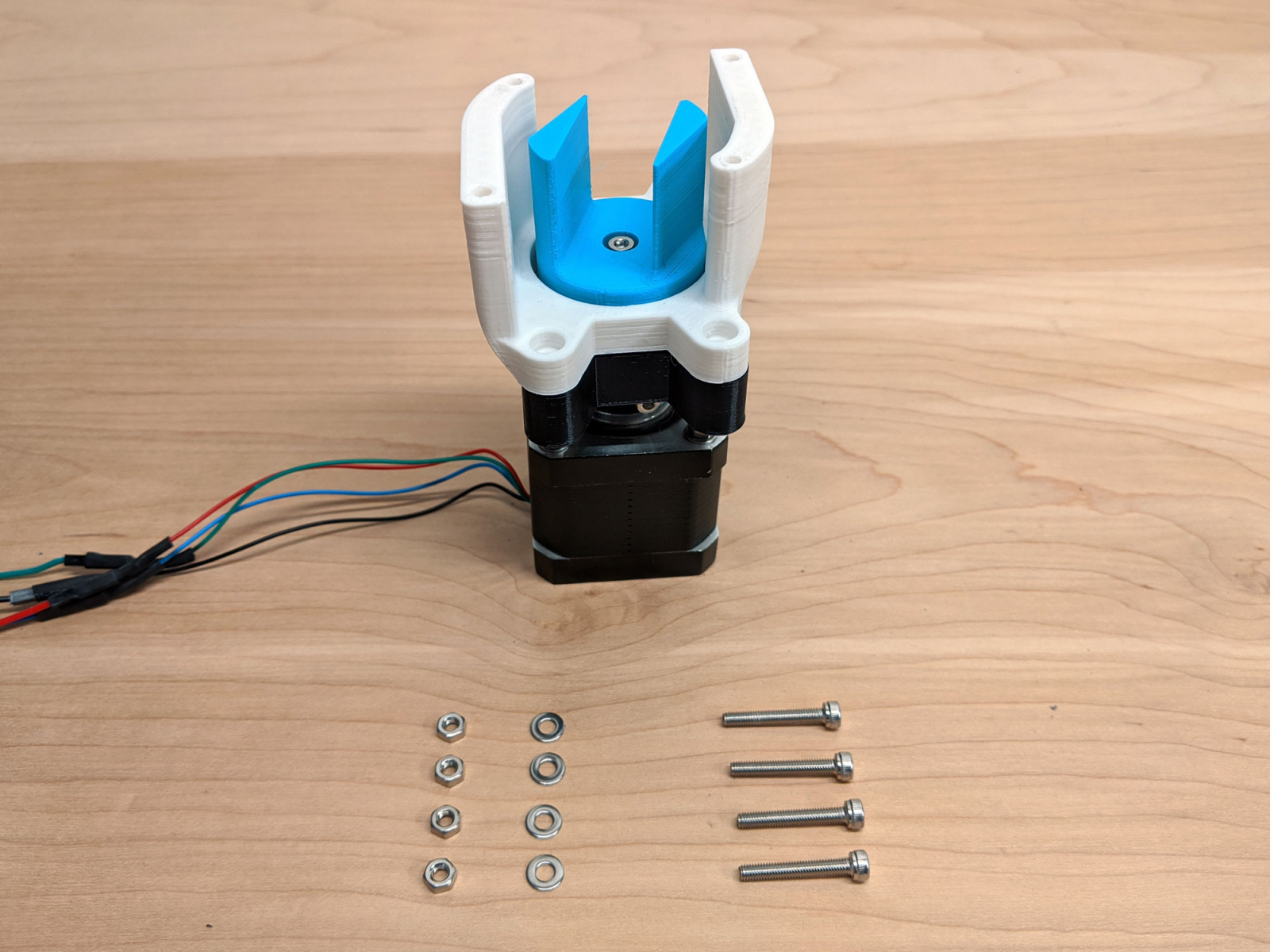 Insert bolts, add washers, and tighten nuts.
 ![]()
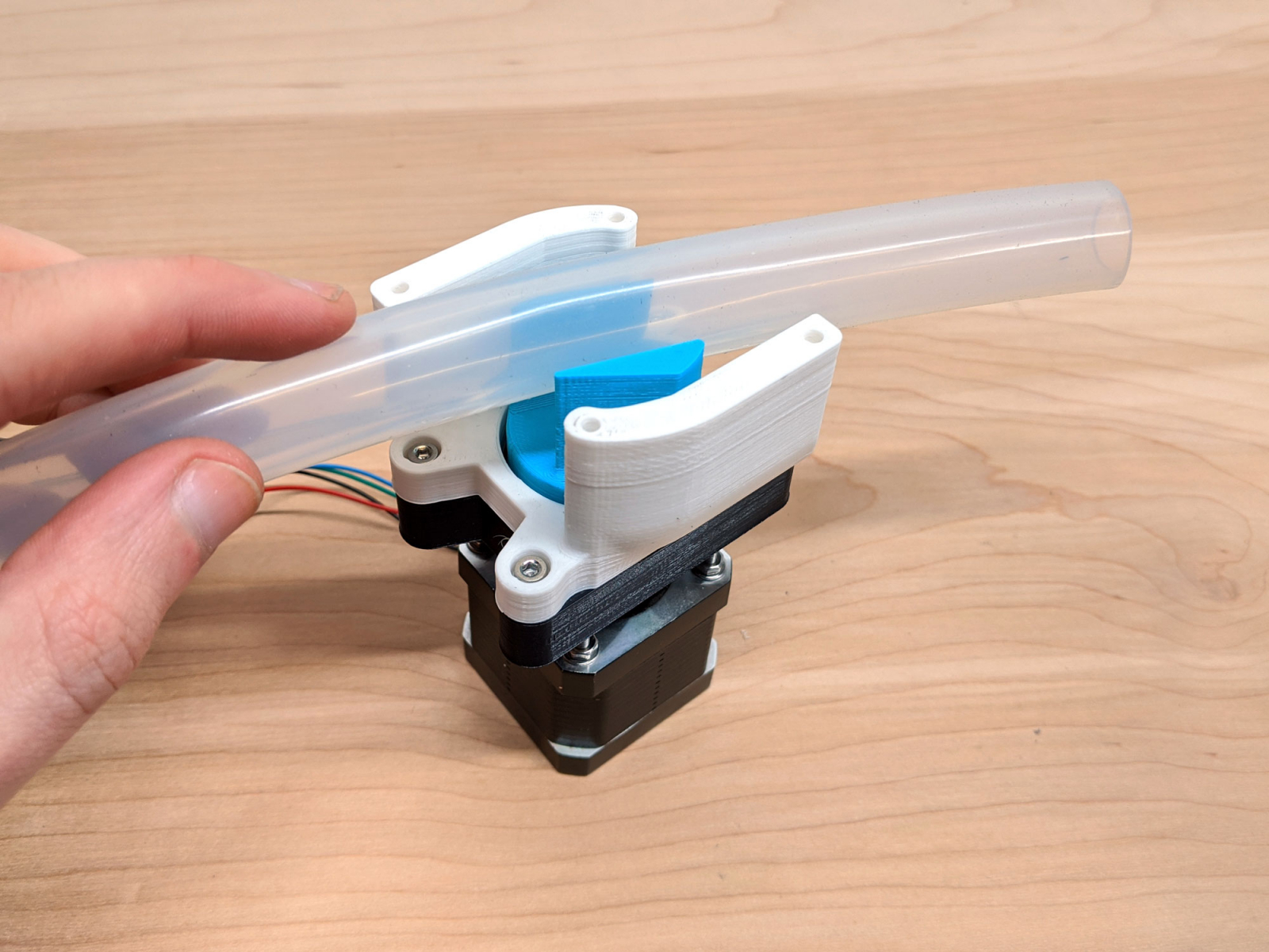 With the blue inner crimper in the "open" position, simply insert the silicone hose.
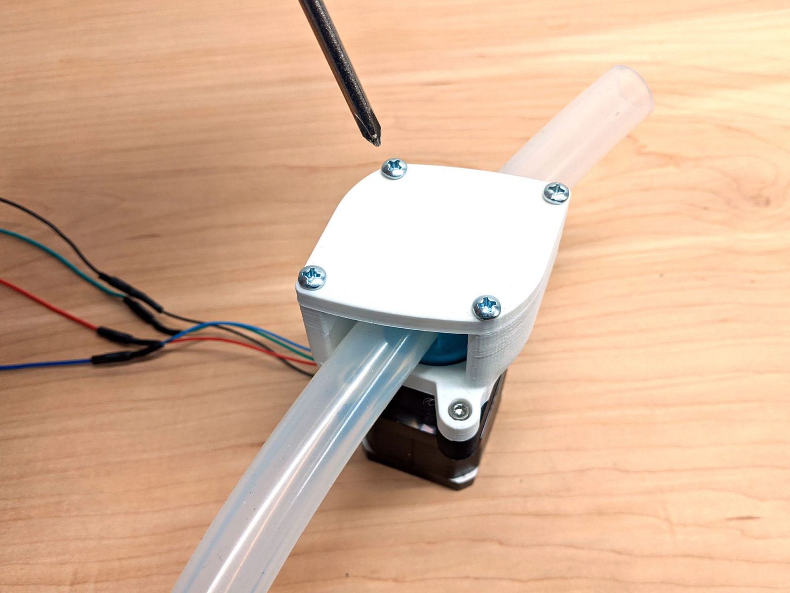 Screw on the outer cover to secure the hose.
Attribution
This design is inspired by annina's Pinch Valve.The 3D print uses a planetary gear box, which is a derivative of Trigubovich's Compact Planetary Gearbox V5.Parts & Tools
- NIMA 17 Stepper Motor (1)
- M3 Nuts & Bolts (Quantity 13, various sizes)
- Screws (4)
- Silicone Tube 1/2" Inner Diameter, 3/4" Outer Diameter
- 2.5mm Alan Wrench
- Screwdriver
- Small File (to clean up the gears)
- STL Files Available Below
Gear Box Assembly
Crimper Module
Attach Assembly to Stepper Motor
somethingCrimper Housing
Hose and Outer Cover